Thanks Ian,
anyone knows if this applies to EL84 boards as well?
I think Ian is referring to the Power Supply boards for the IRF9610 pinout problem not the amplifier boards. I want to start my EL84 build soon and will take a detailed look at the PS board.
Sorry to pepper you guys but 3hrs down the track with luddite pencil and paper design, I am convinced we have a problem.
The source and Drain connections to that IRF9610 are REVERSED......snip
Good catch Ian, you know I never even looked at that circuit, just built it. But now that I look at it, that 9610 doesn't appear to be doing anything at all the way it's connected. Glad you referenced the circuit as I am still getting my head around what that is suppose to do.
But you're way smarter than I am, so thanks for digging into that a bit.
Would be nice if Marc was around, I sure hope he's doing ok as he had some medical issues. Would be nice to hear his comments and where he came up with that circuit. There are a few other pieces of that PSU that are head scratchers too.
gabo
Sorry to pepper you guys but 3hrs down the track with luddite pencil and paper design, I am convinced we have a problem.
The source and Drain connections to that IRF9610 are REVERSED.
The power supply is working to give you full voltage and full ripple because the bulk diode which is intrinsic to the MOSFET is forward biased and is effectively taking the MOSFET out of circuit.
Also several component values are suboptimum or worse.
What do we need to fix it?
First we need to isolate the MOSFET Drain and Source connections:
So
Do not fit (or remove) R1, R6 and D8
Next make a new Drain connection:
Wire from R6 pad next to the big 2200uF/25V cap to the R1 pad which is closest to the board edge. Note: rather than a wire link you can use a low value resistor, say 47 Ohms which acts as a Drain Stop resistor against oscillation,. Rarely required, just use a piece of wire
Next make a new Source Connection:
Wire from D8 Cathode Pad to The R6 pad which joins C6. I strongly recommend that in this case you use a 100 Ohm resistor to make this link (see below).
WE need to restore the protection diode, the old anode connection is fine but the cathode needs to connect to that R6 pad which joins C6 noted above. Why not to the Source directly? This is a Gingertube "smart ****" mod, by connection the output side of the 100 Ohm mentioned above we add current limiting protection to the supply. Since Mosfet Gate/Source Thresholds are all over the place (IRF9610 says min 2V max 4V) that will introduce a 20 to 40mA current limit if the output gets shorted. AOT (Adjust on Test which is the shorthand form of the "design engineer saying he really doesn't know").
Next R2 is way too high. The circuit operates by limiting output voltage to just less than the lowest dip in the input voltage. So R2 should drop a DC voltage of at least the maximum peak to peak ripple voltage from the raw supply. This is a lowish current supply and ripple is unlikely to be huge so I would try 22K for R2. A higher value means more immunity to ripple but also a lower output voltage and more dissipation in the MOSFET.
I will actually be building my board this way and will report when running.
Would be glad to hear someone say I think your WRONG but this is my current thinking.
Cheers
Ian
Edit/PS How important is a low ripple -ve supply. For the BH its is far less important than usual. The current source loads on the Source Followers isolate -ve rail noise and the bias feeds have additional dropping resistors and filtering. So you may consider a 90% fix as just leaving everything as is, or removing the mosfet and putting a diode from Drain to Source, which is what you have now.
But to be OCD and have the cleanest B- and bias supplies the mod should do it.
Hello Ian,
Can you post a modified diagram to us?
I just looked closely at the schematic for the first time. The 9610 is reversed d-s on the schematic, so that got produced on the pub as well. To me it looks like the easiest way to correct this is just to install the 9610 with the d and s leads reversed. If you are using a heat sink and can leave the leads longish you have the space to carefully bend them to fit and insulate them from each other with heat shrink or wire sleaving. You could also cut the 2 leads off just a bit below the thicker portion that goes into the body of the transistor and solder short wires to the stubs that connect to the proper spots on the board. Providing the board is true to the reversed layout of the 9610 you will not need to change the board at all. I have done this in the past when replacing unavailable TO220 power transistors with substitutes with different pin outs and never had an issue. Solder carefully and take your time doing it.
Looking at the resistor values in the circuit - The ratio of R2 and R3 set the output voltage. The output voltage will be approximately- Vin x( R3/r2+R3)-4v . The 4v is the approximate Vgs of the 9610. So for R2 470k, R3 1meg, vin 100v we end up with V out of about 64 volts. So you cannot randomly change R2 and R3 without considering the output voltage that results. R4 and C4 set the time constant for the cap multiplying filter function of this circuit. I have been using a variation of this method in my tube amps for 20 years. A long time constant for R4 C4 gives you a soft start, with the voltage rising slowly to it’s final value. Lowering R4 will speed this up.
Looking at the resistor values in the circuit - The ratio of R2 and R3 set the output voltage. The output voltage will be approximately- Vin x( R3/r2+R3)-4v . The 4v is the approximate Vgs of the 9610. So for R2 470k, R3 1meg, vin 100v we end up with V out of about 64 volts. So you cannot randomly change R2 and R3 without considering the output voltage that results. R4 and C4 set the time constant for the cap multiplying filter function of this circuit. I have been using a variation of this method in my tube amps for 20 years. A long time constant for R4 C4 gives you a soft start, with the voltage rising slowly to it’s final value. Lowering R4 will speed this up.
Last edited:
Thanks, yes it does look like that just swapping the d-s leads will work.
Also be aware that the original schema has C4 at 2uf. However, I was unable to find a suitable 2uf cap that would fit the board. In the BOM for the PSU, C4 is listed as .15uf and the specified cap does fit the board.
To make sense of it, I set it up in ltspice to model it. With the specified 2.2M for R4 and the .15uf cap from the BOM, it takes about 1.5 seconds to reach full voltage. With the original 2uf cap, it takes about 14 seconds. To get that much time you'll need an R4 that is very large, like 30Meg or so. Of course there is no need to go that high, 10meg gives about 5 seconds. I'm not sure how long we need here, even the 1.5 seconds gives a soft start.
Also on my build (with the 9610 connected wrong) I was getting about -107 v for the output voltage. Swapping the d-s around is going to change that to around -70v or so. The schema specs -135v, which I don't think is even attainable. I'll have to do some more thinking about what is optimum for that voltage and possibly adjust R2/R3 appropriately.
thanks, gabo
Thanks, yes it does look like that just swapping the d-s leads will work.
Also be aware that the original schema has C4 at 2uf. However, I was unable to find a suitable 2uf cap that would fit the board. In the BOM for the PSU, C4 is listed as .15uf and the specified cap does fit the board.
To make sense of it, I set it up in ltspice to model it. With the specified 2.2M for R4 and the .15uf cap from the BOM, it takes about 1.5 seconds to reach full voltage. With the original 2uf cap, it takes about 14 seconds. To get that much time you'll need an R4 that is very large, like 30Meg or so. Of course there is no need to go that high, 10meg gives about 5 seconds. I'm not sure how long we need here, even the 1.5 seconds gives a soft start. It is more of an issue with KT88 than EL34 types. KT88 can run -40-45 volts if you use high B+ voltages. That is where you get a requirement of 3x45=145 volts.
Also on my build (with the 9610 connected wrong) I was getting about -107 v for the output voltage. Swapping the d-s around is going to change that to around -70v or so. The schema specs -135v, which I don't think is even attainable. I'll have to do some more thinking about what is optimum for that voltage and possibly adjust R2/R3 appropriately.
thanks, gabo
Yes, you can use whatever RC combination you like to get the time constant you need. I tend to use larger caps and smaller R. I have used electrolytics in this role in the past and they work just fine. They will have some leakage current but it all stabilizes and offers good performance IME. Using really small caps they will have a significant Xc at 120hz and raise the impedance going into the gate. That could end up causing a bit of hum pickup.
I built my BH el34 using the original boards and did a regulated bias voltage setup. I had stuffed the amp boards with 100v bypass caps for the incoming bias voltage and that is a limit that you need to note if you are going with a higher V- for the driver. I’m not sure how the new amp boards are configured.
I originally wanted to build the EL84 version but got sucked into the el34 vortex and ended up doing it with KT88s in mind. I have a lot of KT88s around here so it’s a natural fit for me. I am going to look at that amp again. It seems to sound thin in the midrange for some reason. I am going to have a go at adjusting the shunt feedback resistors and also lowering the screen voltage a bit using zeners. I am using Toroidy outputs and they have a very low series resistance which means that the screens run at a higher voltage than with a conventional transformer. I’ll see how all this plays out. I am itching to start my EL84 build and am just finishing a solid state USSA5 build, so lots of stuff on the boil here.
PS if you measure the - bias voltage at the output tube control grids while at your intended operating point, you can determine how much voltage you need going in. You need to swing at least twice the bias voltage at the grid and then you need a voltage of say 20v to keep the driver from cutting off. So for instance at -30v bias it looks like -80v would do it. I think you could also use the short cut of 3 x the bias voltage.
Here is a link to the spot in the thread where I was building my KT88 version.
[https://www.diyaudio.com/forums/tubes-valves/326920-el34-baby-huey-amplifier-46.html#post5791015
Last edited:
Yes, you can use whatever RC combination you like to get the time constant you need. I tend to use larger caps and smaller R. I have used electrolytics in this role in the past and they work just fine. They will have some leakage current but it all stabilizes and offers good performance IME. Using really small caps they will have a significant Xc at 120hz and raise the impedance going into the gate. That could end up causing a bit of hum pickup.
I built my BH el34 using the original boards and did a regulated bias voltage setup. I had stuffed the amp boards with 100v bypass caps for the incoming bias voltage and that is a limit that you need to note if you are going with a higher V- for the driver. I’m not sure how the new amp boards are configured.
I originally wanted to build the EL84 version but got sucked into the el34 vortex an needed up doing it with KT88s in mind. I have a lot of KT88s around here so it’s a natural fit for me. I am going to look at that amp again. It seems to sound thin in the midrange for some reason. I am going to have a go at adjusting the shunt feedback resistors and also lowering the screen voltage a bit using zeners. I am using Toroidy outputs and they have a very low series resistance which means that the screens run at a higher voltage than with a conventional transformer. I’ll see how all this plays out. I am itching to start my EL84 build and am just finishing a solid state USSA5 build, so lots of stuff on the boil here.
PS if you measure the - bias voltage at the output tube control grids while at your intended operating point you can determine how much voltage you need going in. You need to swing at least twice the bias voltage at the grid and then you need a voltage of say 20v to keep the driver from cutting off. So for instance at -30v bias it looks like -80v would do it. I think you could also use the short cut of 3 x the bias voltage.
Here is a link to the spot in the thread where I was building my KT88 version.
[https://www.diyaudio.com/forums/tubes-valves/326920-el34-baby-huey-amplifier-46.html#post5791015
For the kt88 shouldn't it be better to stay with a voltage higher than 100v?
Cordialy
Yes, you can use whatever RC combination you like to get the time constant you need. I tend to use larger caps and smaller R. I have used electrolytics in this role in the past and they work just fine. They will have some leakage current but it all stabilizes and offers good performance IME. Using really small caps they will have a significant Xc at 120hz and raise the impedance going into the gate. That could end up causing a bit of hum pickup.
Good to know, I probably have an electrolytic that will work to raise the C4 cap value.
PS if you measure the - bias voltage at the output tube control grids while at your intended operating point, you can determine how much voltage you need going in. You need to swing at least twice the bias voltage at the grid and then you need a voltage of say 20v to keep the driver from cutting off. So for instance at -30v bias it looks like -80v would do it. I think you could also use the short cut of 3 x the bias voltage.
FYI, I'm also using KT88s.
I think I'm good here, I'm at around -51v bias on the output grids and have 188v coming in.
I've actually been listening to my amp (with the 9610 in the PSU reversed) for over a month and it sounds great! Fortunately this is all good timing as I disassembled the amp to paint and do some chassis work, so I can take this opportunity to fix the 9610 issue.
My only concern is that I don't want to screw up the way it sounds
")
The only real change will be the taking that -vbias from -107 to around -70. If that causes a problem, I can either adjust R2 in the PSU or adjust R16 on the channel boards.
gabo
To me it looks like the easiest way to correct this is just to install the 9610 with the d and s leads reversed. ..... Providing the board is true to the reversed layout of the 9610 you will not need to change the board at all. <snip>
A long time constant for R4 C4 gives you a soft start, with the voltage rising slowly to it’s final value. Lowering R4 will speed this up.
Thanks for your confirmation of an “easy” fix.
I have a further question (while your are dealing with the PS). It seems to me that using the second regulator (LM317) to provide regulated power to the drivers would be better use of it, than operating a relay. But I don’t know if the ~12Vdc resulting would be insufficient for the drivers. What do you think?
I posted this over in the group buy thread as well.
I had just replied there.
Last edited:
Thanks for your confirmation of an “easy” fix.
I have a further question (while your are dealing with the PS). It seems to me that using the second regulator (LM317) to provide regulated power to the drivers would be better use of it, than operating a relay. But I don’t know if the ~12Vdc resulting would be insufficient for the drivers. What do you think?
If you have enough input voltage to the regulator you could bump up the output voltage to somewhere just below the max ps volts for the 555 timer IC , which I just noticed is also powered by the lm317, and power the driver with it. To power the relay you could simply put a voltage dropping resistor in series with the relay to drop the voltage to 12volts at the rated relay current. Just make sure you have enough current and voltage available to the lm317 and that the heatsink and series resistor can deal with the heat involved. Check your actual 555 part number to get the max power supply voltage spec. There are different versions out there.
This may seem like some work but if it gets rid of an extra power supply then it’s worth it.
Last edited:
The advantage is that the time constant offered by the RC network at the gate of the series mosfet pretty much sets the low frequency cutoff for noise at the power supply output. So you can get a lot of power supply ripple rejection vs just using bigger capacitors. Ripple rejection can be 60db or more, leaving you with milivolts of noise instead of volts on your B+ voltage. Bigger capacitors are, well, bigger, and also more expensive than the multiplier and will not give you nearly as low ripple. You also get to adjust the voltage easily, provided you are not wanting to go higher than the circuit will allow.
The soft start function is a good thing for output tubes and filter capacitors.
Disadvantages are - complexity, you loose a bit of output voltage if you are trying to get maximum voltage out of a power supply, the circuit can oscillate if you don’t have a large enough gate stopper resistor and you have to make sure you have a big enough heatsink on the series element to keep it from getting too hot.
I have used them for 20 years now in everything from a big PPP kt88 amp (415 volts at .6 amps) to preamps.
Check out this link for some info!
Transistor Capacitance Multiplier Circuit Design >> Electronics Notes
Last edited:
The advantage is that the time constant offered by the RC network at the gate of the series mosfet pretty much sets the low frequency cutoff for noise at the power supply output. So you can get a lot of power supply ripple rejection vs just using bigger capacitors. Ripple rejection can be 60db or more, leaving you with milivolts of noise instead of volts on your B+ voltage. Bigger capacitors are, well, bigger, and also more expensive than the multiplier and will not give you nearly as low ripple. You also get to adjust the voltage easily, provided you are not wanting to go higher than the circuit will allow.
The soft start function is a good thing for output tubes and filter capacitors.
Disadvantages are - complexity, you loose a bit of output voltage if you are trying to get maximum voltage out of a power supply, the circuit can oscillate if you don’t have a large enough gate stopper resistor and you have to make sure you have a big enough heatsink on the series element to keep it from getting too hot.
I have used them for 20 years now in everything from a big PPP kt88 amp (415 volts at .6 amps) to preamps.
Check out this link for some info!
Transistor Capacitance Multiplier Circuit Design >> Electronics Notes
Bfpca I thank you
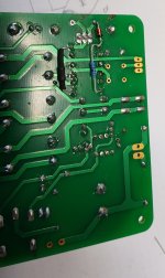
OK here is the back of my modified board.
R1, R6, and D8 removed from board.
R2 changed to 22K
C4 C5 and C6 all 0.15uF 160V caps
The "black" connection is a heatshrinked 10 Ohm resistor and makes the new Drain connection from the raw supply. Using old R1 and R6 pads. Could have just used a piece of wire for this connection.
The 100 Ohm resistor is the new Source Connection using the other old R1 and R6 pads.
Add the Protection Diode (Old D8) back in. The old anode connection for D8 stays the same but the cathode connects to the other side of the 100 Ohm resistor.
That's it, the total mod, turned out quite neatly. No need for cut tracks, Bent MOSFET leads or anything else.
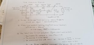
Tested it with a small tranny:
33.2V AC input
Into an 11K Ohm Load I saw:
Raw DC at MOSFET Drain of -88.9 Volts
Filtered DC at output into that 11 K Load -82.5V
That means I was delivering 7.5 mA output.
This indicates it is working correctly.
Haven't tested the over current function BUT am confident it will work. Need to test to make sure it operates at well above the actual current drawn, this because the last thing you need in a tube amp is the bias supplies unexpectedly shutting down.
Cheers,
Ian
R1, R6, and D8 removed from board.
R2 changed to 22K
C4 C5 and C6 all 0.15uF 160V caps
The "black" connection is a heatshrinked 10 Ohm resistor and makes the new Drain connection from the raw supply. Using old R1 and R6 pads. Could have just used a piece of wire for this connection.
The 100 Ohm resistor is the new Source Connection using the other old R1 and R6 pads.
Add the Protection Diode (Old D8) back in. The old anode connection for D8 stays the same but the cathode connects to the other side of the 100 Ohm resistor.
That's it, the total mod, turned out quite neatly. No need for cut tracks, Bent MOSFET leads or anything else.
Tested it with a small tranny:
33.2V AC input
Into an 11K Ohm Load I saw:
Raw DC at MOSFET Drain of -88.9 Volts
Filtered DC at output into that 11 K Load -82.5V
That means I was delivering 7.5 mA output.
This indicates it is working correctly.
Haven't tested the over current function BUT am confident it will work. Need to test to make sure it operates at well above the actual current drawn, this because the last thing you need in a tube amp is the bias supplies unexpectedly shutting down.
Cheers,
Ian
Attachments
Last edited:
The 80 to 100mA overcurrent is intended as a "gross" limit only (blow up proofing).
At 100mA the dissipation in the 100 Ohm Rmod2 will be 1Watt. Over that the supply voltage will dip and its dissipation will dip with it according to voltage squared. So I would not use anything less than a 100 Ohm 2W for Rmod2. I will change the 100 Ohm 0.6W I put in the mod to a higher power rating resistor.
0n 2nd thoughts I will change it to 180 Ohms 1 Watt for over current at 44 to 55 ma.
That is it for today. Everything turned off, workshop shut and alchohol poured.
Hope these "ravings" are helpful.
Cheers Ian
Last edited:
- Home
- Amplifiers
- Tubes / Valves
- EL34 Baby Huey Amplifier