Hi my friends,
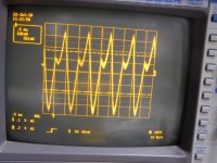
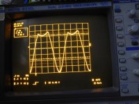
I have a Sonic Frontiers Power 2 on my table, the problem is a strange distortion on left channel. The fist interchange the tubes from left and right channel, the problem it the same.. on C28 with only R ch there is a normal sine wave without distortion, in the C29 there is a orrible wave, you can see on the picture, more and the signal is more high that other channel, but in a video there is another strange problem... when I put in signal in Right channel, the signal out in another channel ( left it's more low) but I put signal in a Left channel the signal go out also from the right .. more low this is a strange..
look my demo video.. YouTube
Someone can help me ?
Attachments
Last edited:
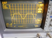
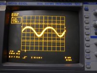
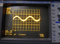
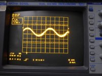
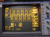
Hi, I tryed in balanced, and unbalanced, the same problem. Trying with only R channel I can see a normal sine wave on a pin 3 (grig) on V2 Tube 1 Volt amplitude, the same misure on the other channel, and on pin 7 (catode) on V2 Tube there are 4 Volt normal sine wave.
On pin 7 in the other channel ( fail channel ) I measure a distorted wave with a 15 Volt amplitude !!!
you can see the picture.
On pin 7 in the other channel ( fail channel ) I measure a distorted wave with a 15 Volt amplitude !!!
you can see the picture.
Attachments
Last edited:
> The power are ok V3 and V3/2
Channel OK Plate 128 V Catode 131 V
Plate lower than Cathode is almost certainly wrong.
It is very hard to read your thumbnail schematic. However I squint V3 cathode as 5.8V, not 100-something Volts.
My guess is that Q19 Q21 are not dong their jobs, but there are many possibilities. Lot of parts in there. You want to understand the actual problem, not "shotgun" new parts in hope of hitting the trouble.
The cap is OKI would also check to make sure the 0.1uF cap in front of pin 7 is not leaky.
You are right, but when I measure ... it was 1 am ... and was the measure before the bed> The power are ok V3 and V3/2
Channel OK Plate 128 V Catode 131 V
Plate lower than Cathode is almost certainly wrong.
It is very hard to read your thumbnail schematic. However I squint V3 cathode as 5.8V, not 100-something Volts.
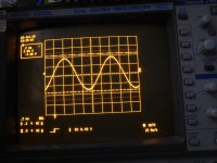
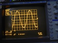
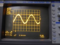
The correct measure are :
CHANNEL FAIL V3/1 pin 1 (plate) 134 V pin 2 (grid) 2.5 V pin 3 catode 5.7 V
pin 6 (plate) 127 V pin 7 (grid) 2.8 V pin 7 catode 5.5 V
CHANNEL OK V3/2 pin 1 (plate) 131 V pin 2 (grid) 2.7 V pin 3 catode 6 V
pin 6 (plate) 127 V pin 7 (grid) 3 V pin 7 catode 5.7 V
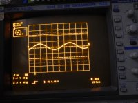
the scope measure on the plate, and catode with the same signal
there are three stranger things:
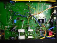
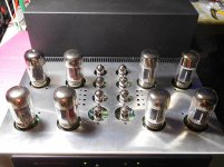
on the board, fists 4 tube are: V1 V2 V3 V4... but in electric diagram there are V1 V3 V5 V7
my measure are the same of the electic diagram !!
the second thing is: on a socket of V2 there is soldered, a serie of capacitor an resistor (on the board) or V3 in electic diagram, but there isn't in a diagram ...
and the last is an interference when 1 channel is mute and the other in on there is a normal signal out of channel in use, but a little signal from the channel in mute. .. this is strange..
my referiment and measure are refered to Electric Diagram..
To my opinion the problem is around this tube...
I hope that I'm cleear in my explain. Thank you for your help !
Attachments
-
 Board.jpg204.8 KB · Views: 78
 -
 Plate_pin_6_ch_OK.jpg115.2 KB · Views: 48
 -
 Plate_pin_6_ch_FAIL.jpg122.4 KB · Views: 37
 -
 Plate_pin_1_ch_OK.jpg112.6 KB · Views: 40
 -
 Plate_pin_1_ch_FAIL.jpg122.9 KB · Views: 43
 -
 Catode_pin_8_ch_OK.jpg159.8 KB · Views: 30
 -
 Catode_pin_8_ch_FAIL.jpg157 KB · Views: 121
 -
 Catode_pin_3_ch_OK.jpg157.7 KB · Views: 124
 -
 Catode_pin_3_ch_FAIL.jpg155.7 KB · Views: 126
Last edited:
Hi guys,
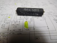
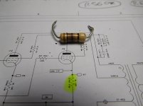
I found the problem, the main problem was R59 V5 plate resistor was broken, and in second into the other channel RA8 situated of V7 plate, it had been replaced before my reparation, with a wrong value, you can see the pitcure 10 ohm .. but it's more long of his value, with the multimeter I read 47 Ohm, but the correct value was 5.1 Ohm.
Replaced these component .. the output is perfect ...
Attachments
Last edited:
- Status
- This old topic is closed. If you want to reopen this topic, contact a moderator using the "Report Post" button.
- Home
- Amplifiers
- Tubes / Valves
- Sonic Frontiers Power 2 strange distortion