What is the class A limit of your 25W design? How much power would it make into 64 ohms?
Class A is possible with OTL by applying constant plate voltage supply system such as Class G (Class A + Class C), say a constant supply of 120V so the bias can be as low as -25V, this greatly increased the Class A portion and distortion is much reduced. Most 6c33c OTL can output 50W into 32 ohms but the power is tapered off for higher load due to high swing that hit the limit of power supply usually 140V-170V, if higher voltage is used 60W into 64 ohms is quite possible.
6P3S and 6P1P both work for years at high power levels in my set up.
I also have a commercial tube receiver that was never turned off and the ECL82 tubes lasted 5 years before I changed them to 6F3P. They were weak but still functional. They were the original tubes from the 70s, so they lasted 25 years before I got the amp in the first place. 30 year tube life
What is the class A limit of your 25W design? How much power would it make into 64 ohms?
")
Without further details about the usage the receiver got during the 25 years before you acquired it, that is not particularly informative.
The quiescent current in the tubes in an OTL with two 6C33C output tubes is about 200mA typically, so that would mean the amplifier operates in class A up to about 600mW (with 8 ohm load). OTLs typically operate in class AB, except at very low powers.
What really is the point you are trying to make? You evidently don't like OTL amplifiers, but many of the objections that you are raising, or implying, are rather off-target. They can achieve very low output impedance, excellent low-distortion performance, large and very flat bandwidth, and the output tube life is very good. Declaring rather implausible goals of running tube amplifiers at maximum output power continuously for years on end seems to be a bit pointless.
The existing driver should be able to drive extra pairs, and only need about 100V-p to drive 3 pairs of 6c33c to full output @-50V bias
I don't know what you mean by existing driver? I use a split load and in order to get high enough voltage for 4 tubes fed by 175V, (175V is needed to get 80W from four 6C33C) my choice was to reduce current in the split load thereby increasing swing and to add cathode followers DC coupled to the 6C33C grids. I see that you have 220k as grid leak for the 6C33Cs, that is on the limit, less than 100k is better from my experience. 6C33C start to draw grid current when close to 0V so if you want to drive it to that point you need to provide some drive current.
Most of the Spice models for 6C33C is really bad as they don't include the odd behavior at low currents, (there is a "kink" in the anode curve) and they don't model grid current behavior close to 0V well either
What is the class A limit of your 25W design? How much power would it make into 64 ohms?
As cnpope wrote the quicent current is 200 - 300mA so power at constant current, (if you call that class A) would be up to about 0.5W.
Power in 64 ohm is limited by the anode voltage in my 25W design as it is optimised for giving max power in 8ohm and minimum anode dissipation.
If you would increase anode voltage you could theoretically get more than 100W from one pair, the limitation in this case would be the allowed max anode voltage as it should not be higher than 250V for 6C33C.
I don't know what you mean by existing driver?
The gain of 4 pairs 6c33c is 1.4, not much more drive is required than 3 pairs, as it needs only 100 V-p drive level, this would give you over 100 watts (45V-p, 31V rms) into 8 ohms, you need only 150V power supply as the sim shows, is there something wrong here in the sim, the kink you mentioned does it matter here?
The existing driver in the amps mentioned in the earlier post such as Tim Mellow can handle that. However if the bottom tubes gain is intentionally reduced (by mean of NFB for instant) , it then required more drive level to get the same output as if gain were un-attenuated.
Last edited:
The gain of 4 pairs 6c33c is 1.4, not much more drive is required than 3 pairs, as it needs only 100 V-p drive level, this would give you over 100 watts (45V-p, 31V rms) into 8 ohms
Yes, maybe but I get 80W with 2 pairs! I can get 100W but I use equalising resistors in the anodes to even out differences between tubes, this reduce output power. In order to use 4 pairs, (8 tubes) you would need to match them very closely or to use large equalising resistors or it would not work. I think it is better and easier to use fewer tubes with a bit higher anode voltage, (higher anode voltage is needed to cater for the increased output voltage) and modify the driver for more drive voltage, (grid bias is higher due to higher anode voltage).
is there something wrong here in the sim, the kink you mentioned does it matter here?
I have never found a spice model for 6C33C that is good enough for much more than idle conditions, the best I found was from an organisation in France, Exceem, they also included the kink and verified the model all true the anode voltage range but not for higher currents than 1A, (of course there will be large differences between tube samples, these differences are not shown in the model). The kink affects distortion and bias conditions, a simple model gives either wrong bias or wrong current for small currents.
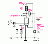
...parallel more than one PL504 to reduce the output impedance so as to be closer to 8 ohms? ...does each tube need to have its own resistors or just parallel them pin by pin?...
Yes. Here is 60 Ohms. Heck of a headphone amp even for modern low-Z phones. 8 Ohm loading suggests 75 PL504s, will make around 0.9 Watts, while eating 560 Watts of 24V power. Per channel!!
BTW, this type resistance-coupled "power" amplifier *sucks*. A choke-loaded power amp can approach 50% efficiency, push-pull can go toward 78% eff. A resistor-loaded amp's best efficiency is a bit over 8.5% MAX. For ideal devices! Using tubes, 4% plate circuit efficiency is fantastically good; counting heater power also the efficiency is about 0.26%.
Attachments
Well, that is a one person's point of view, and many would disagree with him. He obviously has a bit of an "anti OTL" bee in his bonnet.
Turner certainly seems to have that, though he does bring up valid considerations. Any hollow state OTL will be operating into nearly vertical loadlines as you have the complication of trying to make a Hi-Z device operate into Lo-Z loads. Not having "P-Channel" VTs is also another complication.
I have had great success with a variety of different OTL designs. I have never run into problems caused by the negative feedback. I have built OTLs with a very low output impedance, very low distortion, and quite decent output power. (For example, 25W using just a pair of 6C33C tubes.) I've been running some of my OTL amps for years and had no problems with tube failures.
Not that it can't be done, and Ralph Karsten at Atmasphere has done it as well, though some of his designs seem a bit ridiculous. Who needs something like that unless you need to fill a stadium with sound or are plate modulating a big AM rig? This looks like an exercise in "just because we can".
My preference OTL-wise would be hollow state for the front end driving power MOSFETs on the back end. Power MOSFETs in a circletron should sound just as good and you don't need all that extra current to light 'em up. The A Number One problem with MOSFETs is that "complimentary" N-Channel/P-Channel pairs are a good deal less "complimentary" than NPN/PNP complementaries. The circletron answers that problem as you can use N-Channel MOSFETs only.
An OTL with 2 6C33C in inverted Futterman connection can easily give 25W in 8 ohm with high reliability and long tube life. 25W in 8 ohm means that the tubes need to give a peak current of 2.5A and that the average current through the tubes of 2.5/PI or about 0.8A. This exceed the allowed max average current for the 6C33C which is 0.6A and it will also mean that the max allowed anode dissipation of 60W is exceeded.
However as for any amplifier used for playing music the maximum power is never used contionously, music depending on type have a crest factor, (relation between peak and average power level) of 10 - 20dB. So in reality any amplifier even at playing just before clipping level give out a power that is 10 to 100 times lower than maximum.
For the OTL example above with 25W in 8 ohm and a crest factor of 10dB the amplifier give 2.5W average, (if played up to clipping), the peak current will then be 0.79A and the average current through the tubes 0.79/PI = 0.25A which is well inside the limit. The Anode dissipation with 160V anode voltage will then be 40W which is well below the allowed max.
So thats the story on how an OTL can be built with few tubes, (of the right type) and still have good reliability and long tube life.
These days that could be a dangerous assumption. I've seen music compressed to such an extent as to be almost flat across the board. Playing that approaches "brick on the key" operation, so do be careful.
Turner certainly seems to have that, though he does bring up valid considerations. Any hollow state OTL will be operating into nearly vertical loadlines as you have the complication of trying to make a Hi-Z device operate into Lo-Z loads. Not having "P-Channel" VTs is also another complication.
Not that it can't be done, and Ralph Karsten at Atmasphere has done it as well, though some of his designs seem a bit ridiculous. Who needs something like that unless you need to fill a stadium with sound or are plate modulating a big AM rig? This looks like an exercise in "just because we can".
Almost- we've not built very many of that model. But the MA-3 does define the state of the art in many ways- its the most powerful OTL made, and one of the more powerful triode amps made at over 500 watts.
Speaking from experience, its obvious Turner has more than just a bias- he really doesn't know what he's talking about!
Most of our amps are like the M-60 described in the 'what tubes for a tube amp' thread:
What tubes for a OTL tube amp?
The tubes hold up well, vertical load lines notwithstanding, and distortion without feedback is often less than 0.5%THD with IMD below 0.05% into an 8 ohm load at full power (one must be careful not to short the speaker terminals to ground else the distortion and power readings will be a mile off; this measurement problem is a lot harder to avoid than it might seem at first blush), and that's open loop. Such an amp should not exist according to Turner. He must have never actually played with an OTL, best I can make out.
As you point out, the Circlotron obviates the need for complementary devices.
I think the main reason for going OTL is distortion- or the lack thereof. All amps make distortion, and the distortion they make is interpreted by the ear as tonality. This is the 'richness' of SETs or the 'brightness and harshness' of solid state; either way its distortion.
The ear is keenly sensitive to the higher ordered harmonics (which is also easily demonstrated), even in 'trace' amounts of 0.005% its still audible since the ear uses the higher orders to sense sound pressure.
By building a fully differential OTL, you can avoid the more common tube colorations as you won't get the even orders so much, and avoid the brightness often associated with solid state. The result can be astonishingly neutral if one is moderately careful about the speaker load.
Has anyone hooked a scope up to the output with speakers connected to see the waveforms or measure actual distortion with a proper load. My guess is this type of amp performs like an SE tube amp with lower bass extension.
The other test I want to try is a 50w P-P amp driven at the splitter (Concertina) by a solid state amp thereby testing the outputs and transformer for linearity.
the output tube and transformer may be modelled well by a 1 ohm resistor at 50% power levels or less.
The other test I want to try is a 50w P-P amp driven at the splitter (Concertina) by a solid state amp thereby testing the outputs and transformer for linearity.
the output tube and transformer may be modelled well by a 1 ohm resistor at 50% power levels or less.
Yes, I have done to my amplifiers but I don't see any difference compared to a resistive load as long as output power is within what can be achieved with the actual configuration. An OTL gives lower peak power in low impedance loads but as long as output current doesn't exceed what the tubes can give the signal level is not affected. I use feedback to achieve 0.4 ohm output impedance on my 25W amplifiers so they give quite constant voltage output.Has anyone hooked a scope up to the output with speakers connected to see the waveforms or measure actual distortion with a proper load.
Why? it is quite the opposite, and most OTLs gives much better bass extension than any other tube amplifier, I can get full output power at 10Hz or lower and at a level of -3dB from max I easily can flat frequency curve within 1dB to 5HzMy guess is this type of amp performs like an SE tube amp with lower bass extension.
I realised that I can have misunderstood what you meant, If you argue that OTLs go lower in bass than SE or other transformer coupled amplifiers then it is correct. However distortion in OTLs are usually much lower than in SE amplifiers and as most OTLs are push-pull 2nd order distortion is cancelled to a large degree. In my 25W amplifier I get <0.1% distortion, (THD) at 10W output and <0.01%, (THD) at 1W with 27dB feedback.My guess is this type of amp performs like an SE tube amp with lower bass extension.
Last edited:
I realised that I can have misunderstood what you meant, If you argue that OTLs go lower in bass than SE or other transformer coupled amplifiers then it is correct.
Yes, I too was puzzled about that question in stocktrader200's post. I couldn't decide if he was saying he guessed an increased bass behaviour relative to that of an SET, or a reduced bass like that of an SET.
My understanding is that usually SET amplifiers have little or no feedback, and have correspondingly rather high output impedance. This is very different from the situation with many OTLs, which tend to have a lot of feedback and low output impedance (I know there are exceptions to this, of course).
I have noticed in discussions that sometimes people seem to have misconceptions about low output impedance in an OTL with feedback, arguing that it is somehow "fake." However, as I think you are saying, as long as the output current demand does not exceed the limit the amplifier is capable of, the (low) output impedance is perfectly genuine, and the system of amplifier plus load behaves in exactly the way the low output impedance would suggest.
And in fact the caveat "as long as the output current does not exceed the limit the amplifier is capable of" applies not only when discussing OTL amplifiers, but to all amplifiers. The same caveat applies when discussing the low output impedance of a solid state amplifier.
It is really only ever relevant to discuss the performance and the output characteristics of an amplifier when one is not trying to get more current from it than it is capable of supplying!
One thing that puzzles people about OTLs is the fact that they give lower max output power with lower load impedances. This is contrary to the case for solid state where an ideal amplifier would give double output power in half load impedance, e.g going from 8 to 4 ohm.
For an OTL with tubes the limitaton of output power is always due to the maximum current that the tubes can supply, this depends on what tubes are used and also what anode voltage that are applied, higher anode voltage can give higher output current but also increase anode dissipation.
So for an OTL that is optimised to give say 25W in 8 ohm it will not be able to give the same power in 4 ohm but close, the available anode to cathode voltage for 4 ohm load is higher than for 8 ohm load so the reduction in power is not severe, for my 25W 8 ohm amplifier I get 20W in 4 ohm at the same THD, 1%.
However, this reduction in output power does'nt mean that the output level varies if load impedance varies say like when a speaker is used as a load. As long as the power required by the load is less than what the amplifier can give in that load the output level stays constant. Example: the load is a speaker that varies between 4 ohms and 40 ohms, (bass resonance peak) and the amplifier is not driven to clipping, then the voltage level will be almost constant only affected by the output impedance that can be made as low as you want by increasing feedback.
My guess is this type of amp performs like an SE tube amp with lower bass extension.
Don't overlook the fact the poor bass performance is not always due the bottom end extension, any amp should be "tuned" for critical damping the speaker to get good bass response at the bass frequency which OTL amp can be more extended than the SET amp. The quality of the bass is another story..your amp needs to produce it and delivered to the speaker.
I did mean improved bass response by nature of direct output. I also thought that an SE amp has a higher output impedance then a p-p amp or especially transistor amp. Tube amp open loop gain is generally much lower the solid state resulting in a output impedance around an ohm for a damping factor of 8.
This lower damping factor can increase the bass and treble response as the amp outputs more power into higher Z loads then a solid state amp would.
This lower damping factor can increase the bass and treble response as the amp outputs more power into higher Z loads then a solid state amp would.
I did mean improved bass response by nature of direct output. I also thought that an SE amp has a higher output impedance then a p-p amp or especially transistor amp. Tube amp open loop gain is generally much lower the solid state resulting in a output impedance around an ohm for a damping factor of 8.
This lower damping factor can increase the bass and treble response as the amp outputs more power into higher Z loads then a solid state amp would.
Thanks for the clarification of which of the two opposite possible interpretations you had intended!
Incidentally, the way the notion of "damping factor" is typically presented is a somewhat misleading one. It is usually defined as the load impedance divided by the amplifier output impedance, so one gets impressively high numbers for a solid-state amplifier with a very low output impedance. But what is overlooked in viewing the damping factor as a "figure of merit" is that the resistive component of the loudspeaker impedance should actually be added in the denominator, not the numerator, of a meaningful figure of merit. That is to say, the resistive component of the loudspeaker impedance contributes in just the same way as the output impedance of the amplifier itself, as a hindrance towards controlling the damping of the voice coil. In a speaker of nominally 8 ohms impedance, the resistive component is maybe of order 4 to 6 ohms.
This means that provided the output impedance of the amplifier is substantially less than the resistive component of the loudspeaker impedance, very little further improvement in genuine damping is achieved by lowering the output impedance further. For example, an OTL with 0.4 ohms output impedance will be very little less effective than a solid state amplifier at controlling the damping of the speaker voice coil. (As always, subject to the caveat that one is never trying to get the amplifier to pass a higher current than its maximum.)
- Status
- This old topic is closed. If you want to reopen this topic, contact a moderator using the "Report Post" button.
- Home
- Amplifiers
- Tubes / Valves
- transform simple low voltage OTL tube amp into lower impedance by paralleling tubes