There is a noticeable high frequency rise, +3dB at 17K.
There's no overall feedback, so it's not too surprising. You could try adding an RC network across the output transformer's primary, using something like 6.2k 5W, in series with 2nF 600V.
Last edited:
Well that flattens things to +/- 1dB up to 20K -- thanks! How did you arrive at those values? I'm used to seeing Zobels on the secondary side..There's no overall feedback, so it's not too surprising. You could try adding an RC network across the output transformer's primary, using something like 6.2k 5W, in series with 2nF 600V.
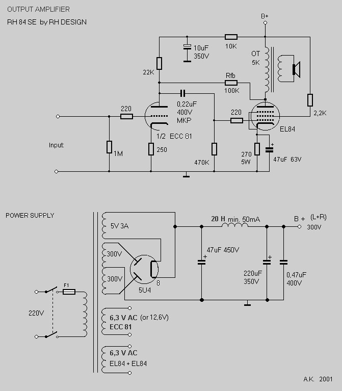
There is something about the RH amp. Take a typical RH feedback resistor of 100K from output tube plate to driver tube plate.
That 100k resistor has to drive the driver tube plate load resistor and driver plate rp, and it also has to drive the driver tube plate capacitance (even though it is not much capacitance). It also has to drive any stray capacitance of the wiring of the driver plate and driver plate load (even though it does not have much capacitance). It also has to drive the output tube control grid capacitance, and all the wiring to the coupling cap, coupling cap to ground, and wiring to the grid. (even though it does not have much capacitance). Add all those small capacitances up, and the negative feedback is reduced at high frequencies. And a reduction of feedback causes an increase of gain.
If that is the case, then a very small capacitor across the 100k Ohm feedback resistor might have corrected the high frequency rise.
But I also like the idea of the Zobel network.
Use what works.
I'll try this too, and get back with findings. How might I accurately choose a value? I appreciate the suggestions but would like to understand the theory as well.If that is the case, then a very small capacitor across the 100k Ohm feedback resistor might have corrected the high frequency rise.
Thanks --
The cap will need to have a voltage rating of more than 2x the B+ (the output tube plate could swing that far). If you first remove the Zobel, and if you have a number of small capacitors, you can try with small values, maybe 47 pF across the 100k Ohm (100k Ohm?) feedback resistor to start. If 17kHz has lower output than 1 kHz, you need less than 47 pF (33 . . 27 . .15pF . .). If the 17kHz still has a rise in output, versus 1 kHz, then try 68pf . . 100 pF . . etc.
The reason I do not have a way to calculate the feedback capacitance, is I do not have enough information about the all the resistances and capacitances that load the plate of the driver tube. But the essence is this: the RC product (R x C) of the feedback cap across the 100k Ohm feedback resistance needs to equal the RC product of the resistances and capacitances at the plate.
Suppose the driver plate (including its own rp) drives 10k of resistance and 50pF. That is 0.5 x 10⁻⁶ (5/10 million). (5/10 million)/100k Ohms = 5 x 10 -12 (5 pF).
5 pF seems a little low, but I have no idea about the capacitances and resistances in the driver plate circuit. This is similar to how an oscilloscope probe is compensated. R x C at probe input = R x C at probe output/scope input. For a high frequency probe, it is much more complex than this.
Well that flattens things to +/- 1dB up to 20K -- thanks! How did you arrive at those values? I'm used to seeing Zobels on the secondary side..
Old tube guy from the 60s.
...How did you arrive at those values? I'm used to seeing Zobels on the secondary side..
With an ideal transformer, it makes no difference pri or sec.
Except to values.
The classic kitchen radio had 100V pentode, 2K OT, speaker. Speaker inductance rose in treble, pentode gave rising response, which is NOT good for AM radio (static).
The fix (before anybody knew Zobel) was a resistor of "matching" value and a cap so it only came-in for treble.
For 2K:4r OT, either 2K 0.02uFd on primary or 8r 10uFd on secondary would work. However the cap must take bipolar signal (so not a cheap electrolytic). 10uFd 6V 'film' did not exist (paper is hundreds of volts minimum rating/size/cost). 10uFd 6V bipolar e-caps were rare. But 0.02uFd 200V was a VERY standard value in tube radio parts bins. So it went on the primary.
Your amp is more like 6K and you want more than AM response, also I assume you are testing on dummy-load not speaker, so Rayma's ~6K 2nFd (0.002uFd) makes sense even without finger-checking.
_I_ would say 2W 400V would be ample for most folks, but these R-C networks DID burn-out a fair amount, and it's not Rayma's money, and 5W 600V is not THAT expensive in DIY-context, no dissent there. And you do seem to be sweep-testing, not just blaring the ballgame, so you "could" put all 5 Watts of power into 20KHz and stress the R-C far beyond any radio would.
Last edited:
_I_ would say 2W 400V would be ample for most folks, but these R-C networks DID burn-out a fair amount,
and it's not Rayma's money, and 5W 600V is not THAT expensive in DIY-context, no dissent there.
And you do seem to be sweep-testing, not just blaring the ballgame, so you "could" put all 5 Watts
of power into 20KHz and stress the R-C far beyond any radio would.
Zobel resistors are often damaged when testing at full power at HF. One Lux tube amp manual recommended replacing the small pcb Zobel resistor with a much larger external one for bench testing.
Last edited:
Well, here's another question if I may. I built an RIAA stage in the spare socket of this chassis. At the grid of the EL84, RIAA EQ looks very good - I have the +20dB at 20Hz. But at the plate of the EL84, amplitude just levels off below 50Hz.
Could this be related to the plate-plate feedback?
Using the RH84 as a line amp, sounds terrific. But I'd love to get it to play well with the phono stage I added, it's just too anemic down low.
Thanks in advance!
Could this be related to the plate-plate feedback?
Using the RH84 as a line amp, sounds terrific. But I'd love to get it to play well with the phono stage I added, it's just too anemic down low.
Thanks in advance!
Well, here's another question if I may. I built an RIAA stage in the spare socket of this chassis. At the grid of the EL84, RIAA EQ looks very good - I have the +20dB at 20Hz. But at the plate of the EL84, amplitude just levels off below 50Hz.
Could this be related to the plate-plate feedback?
Using the RH84 as a line amp, sounds terrific. But I'd love to get it to play well with the phono stage I added, it's just too anemic down low.
Thanks in advance!
RH have input sensitivity of about 1v. Maybe your phonostage output is not big enough to drive the amp to full output.
...at the plate of the EL84, amplitude just levels off below 50Hz....
What transformer??
If the Akai-- deep bass on SE iron is expensive, and Akai may have only given you "so much".
But it also depends on circuit connections, particularly NFB. With NFB I have gotten <<20Hz from a $1 transformer (though only fractions of a Watt).
What is the worst that can happen to your amp after installing the zoebel cap ? Say i start at the 47 pf. Although my RH type amp uses 3K primary impedance outputs to 8 ohm secondary.If you first remove the Zobel, and if you have a number of small capacitors, you can try with small values, maybe 47 pF across the 100k Ohm (100k Ohm?) feedback resistor to start. <snip>
Ok, so I did another round of measurements and realized my first concerns - and adding the Zobel network - were totally erroneous. Sorry for the red herring, must have been a senior moment 
I built this RH84 in Akai M7 chassis. It has two line inputs, and also a 12AX7 phono stage based on the classic RCA manual schematic, with a few tweaks offered by Eli Duttman in older threads.
I'm attaching both the RH84 and the RCA phono schematics. Rather than shoehorn a Mosfet in there, I made an ac coupled cathode follower in the unused half of the 12AT7.
A 100K volume pot is switched between the three inputs.
Using a line input with 1V signal and measuring frequency response across an 8r dummy load, things are flat +/- 1dB from 25Hz to 20KHz. This suggests the output transformer is OK for the audio band, and the RH84 circuit is "sound". -3dB point is 18Hz.
Using the phono input with a 3.5mV signal, I see some interesting things.
Since I'm not too worried about the higher frequencies, I'll just focus on the low end stuff.
At the input of RH84 (12AT7 grid) I see +18dB at 20Hz relative to 1KHz. Reasonably close to +20dB RIAA.
However, at the grid of the EL84, that jumps to +28dB at 20Hz relative to 1KHZ.. Scoping the OT shows gross distortions, probably transformer saturating and who knows what else from the extra 10dB.
Any ideas why 20Hz is being amplified an extra 10dB between the RH84 input and the EL84 grid?
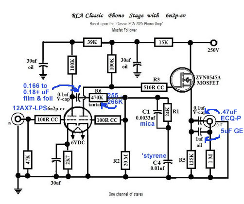
> why 20Hz is being amplified an extra 10dB
It has NFB. That is why the output is "flat" despite non-gigantic output transformer. I bet without NFB the output is down 10dB@20Hz (easily). To make the output flat, something inside the NFB loop must be goosed 10dB.
You can spend several summers (I have) contemplating the wild things which go on *inside* a NFB loop to give the fine final results we enjoy. However on a few-Watt amplifier with a few-buck OT, you can't get a heap of 20Hz, and few-few recordings have genuine 20Hz. (Secret: the majority of Mastering rooms have a 50Hz cut-off.)
- Status
- This old topic is closed. If you want to reopen this topic, contact a moderator using the "Report Post" button.
- Home
- Amplifiers
- Tubes / Valves
- RH84 question