I want to build a PP-Amp with fixed bias. I tried different autobias modules like tentlabs, but they smoked after a while tgem self to death. So, in a perfect world, a switch beteen the measuring resistors, a stationary voltmeter and round knobs to be used without screwdriver would be cool...or is there a better way ? It would be nice to see some pictures ...?
Build the bias supply "simply", which makes it reliable. Don't rely on "gadgets"; instead, use your multi-meter to periodically check O/P tube "idle" current.
If you're worried about bias supply failure, use combination bias and size the wattage of the cathode resistor such that it acts as a fuse. If the bias supply fails and runaway sets in, the cathode resistor "fries" and the O/P tube(s) are spared.
If you're worried about bias supply failure, use combination bias and size the wattage of the cathode resistor such that it acts as a fuse. If the bias supply fails and runaway sets in, the cathode resistor "fries" and the O/P tube(s) are spared.
I've used several Tentlabs autobias units daily for years, so far none of them went up in smoke, it's a reliable product.
Use the fixed bias arrangement that Pete Millet uses on the DCPP (engineer's) amplifier. Simple enough and it will work very well.
What Eli said - though I like to add in current meters so I can easily see the mA flowing through the tube. Make biasing really easy. And given the price of current meters it isn't cost prohibitive.
This module does full auto grid bias like the tent labs design but it's a different circuit and costs less than 1/2 as much. Bias Supply Modul for four Tubes (Single pcb to Control 4 Power Tubes) | eBay
This board makes it quick and easy to set the bias, but it's manual, and must be adjusted periodically. Electron Tube Amp Negative Grid Bias Power Supply Adjustable 4channel for PP SE | eBay
I've used them both and they work great. I prefer the "set it and forget it" approach of the automatic module, but the manual version works fine but should not be used to A2 or AB2 due to the pots being very low power.
I am using all of these already plut the shunt reg of pmillet and the bias regs of Rod Coleman.
The question is more how to physically realize stuff.
So, what Amperemeter or Voltmeter ? Are there difference in terms of audible ? Are amperemeter in series with the electron flow of the cathode ?
So, a multimeter across a 1 ohm resistor best of all or something like this YAMAMOTO PANEL METERS
or is an old voltmeter fine as well ? Switchable ?
or simply banana plugs everywhere for the multimeter...which is not convienent...
I smoked three gen 1 boards of Mr. Tent. Zhey run first perfect, but after 3-4 minth burn down badly. Always with Svetlana el34 sed.
My current Philips El34 change their bias as well nearly each time they start up, so it has become a standatd procedure to check their bias once a week.
Use a voltmeter across a cathode resistor (precision 10R or 1R). You can then make it switchable across all four cathode resistors.
Edit: Or you could hack up a window comparator with led output instead of the voltmeter.
Edit: Or you could hack up a window comparator with led output instead of the voltmeter.
Last edited:
...PP-Amp with fixed bias. ....smoked after a while tgem self to death. .... My current Philips El34 change their bias as well nearly each time they start up ...?
Use Self-Bias Whenever Possible!
When fixed-bias works you can get some/lots more power out of a pair of tubes. But when it does not work things can get very ugly. A 250 Ohm 10W cathode bias resistor is very reliable. After decades of blowing-up tubes (I used to do that a lot in my job) I have mellowed and will accept a reliable 25 Watts rather than 50 Watts on good days and major repairs on other days. (My last major P-P project was down-rating an unreliable 60W amp to a 20W which may out-live me.)
Using a TL783 to set current in place of that resistor making balancing easy, and is just as reliable in most cases.
Only if you like to clip your amp 🙂 You bypass it with a large cap as you would with a resistor, and IMHO what you gain from being able to balance current across the OPT allows the use of toroidal power transformers as OPT outweighs the odd bias shift. They also tend to save the tubes if the grid leak resistor somehow becomes disconnected (ask me how I found out...)
Plus you can design it more elaborately to effectively get a class A system with odd bursts of peak current. I have used this version several times with great success.
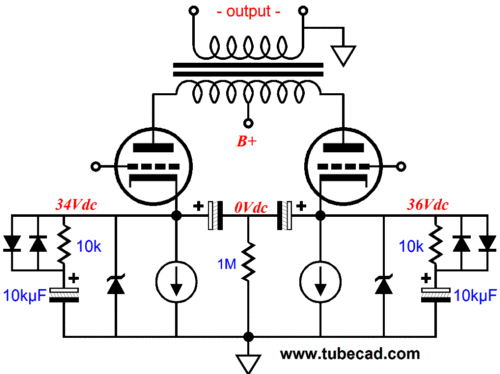
Broskie has some interesting ideas here:
Cathode Bias with a Counstant Current Source
Plus you can design it more elaborately to effectively get a class A system with odd bursts of peak current. I have used this version several times with great success.
Broskie has some interesting ideas here:
Cathode Bias with a Counstant Current Source
Last edited:
Benign clipping behavior is a major trait which separates world class designs from mediocre amps.Only if you like to clip your amp 🙂 You bypass it with a large cap as you would with a resistor, and
The bias shift is more severe with a CCS than with a resistor, even if we're staying in class a.
If we're moving deeper into class ab, it doesn't even work, except for Broskie's kludge, which is a sonic mess.
Use Self-Bias Whenever Possible!
When fixed-bias works you can get some/lots more power out of a pair of tubes. But when it does not work things can get very ugly. A 250 Ohm 10W cathode bias resistor is very reliable. After decades of blowing-up tubes (I used to do that a lot in my job) I have mellowed and will accept a reliable 25 Watts rather than 50 Watts on good days and major repairs on other days. (My last major P-P project was down-rating an unreliable 60W amp to a 20W which may out-live me.)
I wanted to formulate a rebuttal to this, but what I ended up writing was me agreeing with you...
So +1!
That means all self biased designs are marde compared to fixed bias? We're talking about circuit behavior when the circuit is abused, not when used as designed. If I build an amplifier using any number of auto bias schemes, and it puts out 15W of clean sine wave power, I rate it as a 10W amp. Furthermore in actual testing, not SPICE, the amp doesn't exhibit drift until it's severely overdriven. That might be a typical operation for a guitar amp, but those operating conditions don't usually happen in hifi.Benign clipping behavior is a major trait which separates world class designs from mediocre amps.
The bias shift is more severe with a CCS than with a resistor, even if we're staying in class a.
If we're moving deeper into class ab, it doesn't even work, except for Broskie's kludge, which is a sonic mess.
We were talking specifically ccs cathode bias, and yes, it's only acceptable in class a. Which can be push pull class a. With all it's shortcomings.
Occasional clipping & overload is pretty normal use in reproduction of dynamic and / bass heavy audio, especially for low powered (class a) tube amps.
Occasional clipping & overload is pretty normal use in reproduction of dynamic and / bass heavy audio, especially for low powered (class a) tube amps.
What you say is true of truly low powered class designs (<5W), however I find that since 95% of listening happens within the first watt of power (unless you like to crank it, but you wouldn't be using a low powered amp for that) coupled with the fact that my designs using CCS cathodes are usually at least 10W it's usually a non issue. I've even used the CCS scheme pictured about on a push pull KT120 triode amp biased at 90ma with 485V B+. 33W of clean 1kHz sinewave as measured. I've since changed it into a 100W tetrode amp with the auto bias board from audioamp.eu with regulated screens though. This bias doesn't drift very much at all. See this thread for details: Automatic bias board.
Last edited:
Transients can demand a hundred times more power than the average level. A 10W amplifier will clip fairly often.listening happens within the first watt of power coupled with the fact that my designs using CCS cathodes are usually at least 10W it's usually a non issue.
I've never seen a 100V peak on a 1V RMS signal but I'm sure they can if it's one of those test tracks of someone dropping a piano or something. Considering in most music, the RMS is only a couple of db less than peak (don't you just love modern digital engineering, compression, and brick wall limiters?) it's a non issue for me. Those peak transients are so short in duration that the bypass caps and resevoir caps provide the added kick needed in most situations. Just my experience...
- Status
- Not open for further replies.
- Home
- Amplifiers
- Tubes / Valves
- Fixed Bias: How to build it conveniently to use?