I use a kit, its not hum or noise. But after 2 month, 2 of 8 filter cap is swell, i use VOM to check at +-28V pinout, vontage is 32-33V. so I replaced 8 470uF 50V and a 25V 2200uF for filament filter (12.6V pinout have 16V vontage when no tube ) - the board design for 10mm capacitor so I have no choice for larger cap. Beside i change 4 input output cap to Ero MKP cap 1uf.
Im working on a hardwired version of this in a cigar box. Used 50v 470uf nichicon in psu and a 25v 2200uf Panasonic for heater cap. Used some huge 1uf axial polypropylene caps from dayton for my input capacitors. 1.7uf Wimas for output coupling. Ended up keeping the negative feedback loop values at 0.22uf and 200k. I put a shield made from paulownia wood covered in guitar conductive paint between the psu section and the amplifier channels. I also painted the entire inside of the box and grounded the RCA outputs to it. I used a standard stereo a50k vol pot, and put the switch on AC 12v line between the pre and the transformer.
Dead silent with every knob in my system dimed, not a peep. As quiet as my mixing interface and monitor setup. phenomenal performance too. Honestly im blown away. It's instantaneously better imaging no matter what system i hook it up to, even the living room system built around a Yamaha s801 and (old) Klipsch, instant improvement. And i can get a very surprising amount of gain out of it before any perceived clipping, which i can only just barely perceive in the last few % of the volume sweep. Its good enough that im afraid to alter the circuit anymore until i have a deeper grasp on what it is im actually doing. What the negative feedback loop is, how it works, and how you can tune the response and gain of an amplifier only just clicked last night for me, and i felt pretty dumb once it did
Gonna try and get a testing setup put together this week sometime. I really wasn't expecting it to turn out this fantastic. Nor did i expect to be this interested in improving it.
Last edited:
Sorry for another double post, but combining measurment and ear this is where ive landed, and im sticking to it. May help someone who buys this and inevitably lands on this thread.
Output coupling: 3uf film
Input Caps: 2uf film
change resistor following input cap to 22-25k
Negative feedback loop: 220k 0.022uf
Use a transformer/supply greater then 2a current.
Use NoS 6AG5 tubes, ditch the 6AK5 and 6K4, trust me, my soundstage is currently taller, wider, and deeper then i would've even thought possible with my setup.
hand wired version with PSU on a separate board has zero noise problems at all. if not doable the previously mentioned PSU mods remove all audible noise problems
Zero oscillation, no audible low frequency attenuation, under 1db down at 20hz in a 10k input. I cant tell its there at all by ear, and output impedance down to about 800ohms average, . thd under 0.1%. Totally flat from 30hz to nearly 500k. Can get 6-8db of usable, clean gain with no clipping, which is honestly way overkill.
It absolutely does a fantastic example of those imaging benefits that become the attractive aspect of tubes to begin with. It does it VERY well. Will post snips of measurements later this evening.
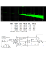
For the comparison reasons I have ran the simulations with Tha(t)oneGuy designs:
#256 => TheStuffMade_1
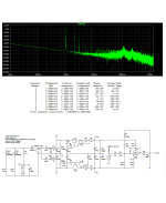
#258 => TheStuffMade_2
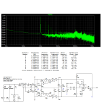
#263 => TheStuffMade_3 (6J1)
#263 => TheStuffMade_3 (6AG5), the spice model used
I could not make the simulation running with 100k in the power supply, they were dropping the voltage efficiently, thus I have changed them to 1Meg.
#256 => TheStuffMade_1
#258 => TheStuffMade_2
#263 => TheStuffMade_3 (6J1)
#263 => TheStuffMade_3 (6AG5), the spice model used
I could not make the simulation running with 100k in the power supply, they were dropping the voltage efficiently, thus I have changed them to 1Meg.
Attachments
The bulk of this “cheap tube preamp” is power supply, and the transistor circuit below has me baffled. What does it do? A pointer to a lecture, article, or online textbook would be much appreciated.
As for the tube part of the circuit, isn’t there supposed to be a bypass capacitor across the 200 ohm R14/R19 cathode resistor?

As for the tube part of the circuit, isn’t there supposed to be a bypass capacitor across the 200 ohm R14/R19 cathode resistor?
Yes TR2 is a current limiter for approx 14ma, but why ?The bulk of this “cheap tube preamp” is power supply, and the transistor circuit below has me baffled. What does it do? A pointer to a lecture, article, or online textbook would be much appreciated.
As for the tube part of the circuit, isn’t there supposed to be a bypass capacitor across the 200 ohm R14/R19 cathode resistor?
View attachment 1281489
as of right now im actually running it directly from a 26v out on a transformer with a bridge rectifier and voltage doubler and some extra filtering. I actually just ditched that transistor section yesterday.
And at least according to a multimeter, 100k in the power supply is very stable voltage output. never drifted by more then 0.1v while reading. Any more and the thing will still arc like 20 mins later, at least in my personal experience with that circuit.
I decided i did not like the design of this power supply as i learned more and more. And the preamp is currently in a pile on my bench again lol. A working pile, but a pile nonetheless. Im gonna need a bigger box. Im actually quickly approaching having nothing left of the original design at this point really.
Funny story, while it was on my bench, i somehow, truly dont know how, i soldered the new -26v to the heater supply pin. God only knows how i did that. The resulting failed transistors and resistors made some real pretty colors and real unfriendly smells.
Last edited:
P.S.
Ditch the 22 ohm resistor feeding the heater circuit if you have this. No idea why they include a 22ohm resistor for that. Even 5654's run at like 5.9v. It's also only a 3 watt resistor and gets hot enough to sizzle water running 300ma. if you put 300 ma heater tubes in pulling 600 total, that resistor will def fry.
a 1.8ohm 5w power resistor has all my 5654 sitting between 6.2-6.5v
a 1.45ohm resistor has my 6ag5 6.1-6.4 and 6AU6 roughly the same. Both offer significant soundstage improvements over 5654 to my ears on my equipment.
As sold, the heater circuit is basically designed to deliver cathode poisoning as fast as possible. My 6AU6 measured at about 5v flat on the circuit stock with the recommended 1a transformer. Which isnt actually enough to run two 150ma heaters and both channels to begin with. Should really stick with 2a minimum transformer regardless of what you do with this circuit
(its far more likely people with curiosity who dont have any idea what they are actually doing, much like myself, (im learning though) will be landing in this thread to find info. Im posting in this fashion for them not you guys lol)
Last edited:
Very good question jcalvarez, it has got me thinking. The only reason the current limiter shall be there, is to limit the plate dissipation. Now the question is what would be the conditions it would make sense. There is one condition to be met in my line of thinking.
Assumption: The power source voltage was originally 24Vac
Calculating with these assumptions we will have +-60V at the rails, which would make it to typical operational voltage for the tube. The maximal plate power dissipation is 1.7W at 200V, at 120V it would make 1.2W corresponding to 10mA limit. Since we want to have some safety margin lets say 25% that would make it to 7.5mA. And that would make sense to me. Running at 120V rail to rail affects capacitor selection for higher voltages (470u/100V), which leads to the elevated production cost and additionally 24Vac might be not that common to find. I believe that was the main reason the circuit was de-tuned for +-30V at rails, but the rest was not recalculated anymore.
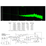
If we agree my assumption is sound, the circuit would look like:

The THD is ~2%, approximately half of produced version, which would also make more sense.


Adding similar offset trick as in my first post we can get down to THD ~0.15%.


Assumption: The power source voltage was originally 24Vac
Calculating with these assumptions we will have +-60V at the rails, which would make it to typical operational voltage for the tube. The maximal plate power dissipation is 1.7W at 200V, at 120V it would make 1.2W corresponding to 10mA limit. Since we want to have some safety margin lets say 25% that would make it to 7.5mA. And that would make sense to me. Running at 120V rail to rail affects capacitor selection for higher voltages (470u/100V), which leads to the elevated production cost and additionally 24Vac might be not that common to find. I believe that was the main reason the circuit was de-tuned for +-30V at rails, but the rest was not recalculated anymore.
If we agree my assumption is sound, the circuit would look like:
The THD is ~2%, approximately half of produced version, which would also make more sense.
Adding similar offset trick as in my first post we can get down to THD ~0.15%.
Last edited:
- Home
- Amplifiers
- Tubes / Valves
- 6J1 China preamp thoughts