I tried re-posting this twice recently to include a new schematic with a power transformer and info but ... now I see it appears on the 2nd page of this post.
---------- here's the latest schematic change --------
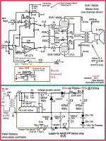
http://pbpix.com/amp/6v6 - 6AQ5 pp-amp-T.png
---------
I have been experimenting on/off with a couple variations of this design for the last 8 years or so.
I found the original 5902 pp version online by Karl Redmer (RVRLABS :: Home) and I built it as he designed it w/standard cathode bias.
I soon began to try different bias schemes and finally settled into the present design using LM317 CCS and set the idle bias for 25ma to run in AB1.
(25 ma bias for 6v6 tubes - and 20ma bias for the 5902 sub-miniature tube design)
I first tried a single ccs per PP pair but soon decided it might be better to physically separate the cathodes and use a separate ccs for each cathode. This is nice because it provides a totally automatic self-adjusting bias for tubes as they age or not perfectly matched.
This scheme requires the addition of a capacitor to re-couple the cathodes together signal-wise. ( I use two e-caps back to back as a non polar cap) This cathode link allows for PSRR (power supply rejection ratio )
I was advised that it would only work in class-A this way unless I by-passed the CCSs directly so that when the signal leaves the class-A zone and enters class-B zone it will find the low-impedance current path through the CCS by-pass caps.
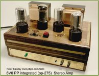
The amp is integrated w/an op-275 pre-amp allowing for a nice clean, simple and easy build as well as having a wonderful sound.
I feed the input on the front panel from an Mp3-player. So volume is controlled on the Mp3-player.
The speakers connect via the 2 RCA jacks.
I re-built the original 5902 version and now also have this nice 6V6 version with the same basic design as the 5902.
I am constantly amazed at the audio quality of both the 6V6 version as well as the 5902 version.
Note: Please do not purchase the op-275 op-amp chips via Ebay as most are counterfeit or fake with a different chip inside. Get them from Mouser or Digikey or any authorized dist.
BTW:
The 5902 schematic and B+ is different from that used in the 6V6 amp so refer to that separate schematic if you use the 5902. The 5902, for only 3 watts/ch is a really powerful sounding amp as well.
You'll notice in the photo of the completed amp I used both octal and 7-pin sockets to allow for either 6AQ5 or 6v6 tubes. I even added an A/B- slide-switch in the filaments to allow for use of the 12V6 or 12AQ5 tubes.
As for the power supply, I chose to use a 'dropper cap' to provide filament power for the four tubes in series. ( 25.2vAC @ 450ma) from the mains.
I have elected to run this power supply w/o an isolation transformer since it's all inside a wood box anyway.
But for anyone who feels this is not a "safe" way to operate, you can easily put an isolation transformer on the power supply and a 6 or 12v filament transformer if you wish.
Here is the 6V6 version:
all info on both the 6v6 and the 5902 versions is available here at my web site:
6V6 Push Pull Integrated Amplifier | 5902 Push Pull Integrated Amplifier | OP-275 6V6 PP Amplifier
Peter Balazsy
6V6 Push Pull Integrated Amplifier | 5902 Push Pull Integrated Amplifier | OP-275 6V6 PP Amplifier
---------- here's the latest schematic change --------
http://pbpix.com/amp/6v6 - 6AQ5 pp-amp-T.png
---------
I have been experimenting on/off with a couple variations of this design for the last 8 years or so.
I found the original 5902 pp version online by Karl Redmer (RVRLABS :: Home) and I built it as he designed it w/standard cathode bias.
I soon began to try different bias schemes and finally settled into the present design using LM317 CCS and set the idle bias for 25ma to run in AB1.
(25 ma bias for 6v6 tubes - and 20ma bias for the 5902 sub-miniature tube design)
I first tried a single ccs per PP pair but soon decided it might be better to physically separate the cathodes and use a separate ccs for each cathode. This is nice because it provides a totally automatic self-adjusting bias for tubes as they age or not perfectly matched.
This scheme requires the addition of a capacitor to re-couple the cathodes together signal-wise. ( I use two e-caps back to back as a non polar cap) This cathode link allows for PSRR (power supply rejection ratio )
I was advised that it would only work in class-A this way unless I by-passed the CCSs directly so that when the signal leaves the class-A zone and enters class-B zone it will find the low-impedance current path through the CCS by-pass caps.
The amp is integrated w/an op-275 pre-amp allowing for a nice clean, simple and easy build as well as having a wonderful sound.
I feed the input on the front panel from an Mp3-player. So volume is controlled on the Mp3-player.
The speakers connect via the 2 RCA jacks.
I re-built the original 5902 version and now also have this nice 6V6 version with the same basic design as the 5902.
I am constantly amazed at the audio quality of both the 6V6 version as well as the 5902 version.
Note: Please do not purchase the op-275 op-amp chips via Ebay as most are counterfeit or fake with a different chip inside. Get them from Mouser or Digikey or any authorized dist.
BTW:
The 5902 schematic and B+ is different from that used in the 6V6 amp so refer to that separate schematic if you use the 5902. The 5902, for only 3 watts/ch is a really powerful sounding amp as well.
You'll notice in the photo of the completed amp I used both octal and 7-pin sockets to allow for either 6AQ5 or 6v6 tubes. I even added an A/B- slide-switch in the filaments to allow for use of the 12V6 or 12AQ5 tubes.
As for the power supply, I chose to use a 'dropper cap' to provide filament power for the four tubes in series. ( 25.2vAC @ 450ma) from the mains.
I have elected to run this power supply w/o an isolation transformer since it's all inside a wood box anyway.
But for anyone who feels this is not a "safe" way to operate, you can easily put an isolation transformer on the power supply and a 6 or 12v filament transformer if you wish.
Here is the 6V6 version:
all info on both the 6v6 and the 5902 versions is available here at my web site:
6V6 Push Pull Integrated Amplifier | 5902 Push Pull Integrated Amplifier | OP-275 6V6 PP Amplifier
Peter Balazsy
6V6 Push Pull Integrated Amplifier | 5902 Push Pull Integrated Amplifier | OP-275 6V6 PP Amplifier
Attachments

Last edited:
Careful:
For those who do not check out pbpix's 5902 schematic, you will have to note:
The 5902 has an absolute maximum plate voltage rating of 165V, an absolute maximum screen voltage rating of 155V, and an absolute maximum plate power rating of 4.1W.
Your mileage may vary (or drop short of your expectations) if you exceed these ratings.
If you put it in a 6BQ5 or 6V6 circuit, it won't work.
Last edited:
Careful:
If you put it in a 6BQ5 or 6V6 circuit, it won't work.
True if you're using fixed bias or a cathode resistor, but with a CCS it'll bias up to 25ma no matter what tube.
The 6V6 / 6AQ5 schematic is only basically similar to the 5902 schematic but the 5902 B+ and bias point is much lower. The 5902 also uses a different (4k impedance) output transformer.
(The 6V6 /6AQ5 in U.L. mode requires an 8k impedance for the OT.)
So yes, in the 6V6 amp you can use either the 6AQ5 or 6V6 tube because they are the same [except pin-out] (but not so for the 5902).
And so, you should follow the specific 5902 print for the correct power and bias settings if you want to build the 5902 version of this fine-sounding but powerful little amp.
Both versions can be found on my website:
6V6 Push Pull Integrated Amplifier | 5902 Push Pull Integrated Amplifier | OP-275 6V6 PP Amplifier
Last edited:
"from the mains" - uh oh.....
As he said, it's in a wood box, and you could use an isolation transformer if you're worried. Countless designs have run off the line with few problems (AA5?), however I'd be apt to use a 120:240 step up and ditch the doubler and a small SMPS for the heaters as I prefer to use aluminum instead of wood.
I did not indicate that anyone should operate the amplifier w/o a transformer isolated power supply.Operating part of, or all of a tube amplifier Directly Off The Mains (no transformer to keep the amp isolated from the mains), and not grounding the amplifier common is not safe!
There may be a web moderator who has a comment on this unsafe operation.
I only stated that for my own personal purposes I chose to operate w/o an isolation transformer but I very clearly stated that for anyone choosing to build the amp they can or should add an isolation transformer for safety.
Operating AF equipment without isolation transformer is a no-go! Yes, you've got it into a nice wooden box, but the RCA input terminals (clearly depicted) are connected to signal ground, with a 50:50 probability of being hot. This device will electrocute you by the same probability!
AA5 is another matter.
Aren't there forum rules that prohibite discussions on things like that?
Best regards!
AA5 is another matter.
Aren't there forum rules that prohibite discussions on things like that?
Best regards!
6v6 or 6AQ5 PP integrated amp w/CCS & P.T.
I am re-posting this 6V6 / 6AQ5 PP amp w/CCS bias.
This new posting includes an isolation power transformer in the supply.
Sorry, I wasn't aware that the forum rules required that.
So I looked at a few aspects of how to address the idea and after several things were considered I decided to go with a single 100VA transformer and leave everything else as it was.
So, ok,.. I did some homework and found that a good transformer solution for this amp is the:
Triad N-77U
100VA
Dual primaries
I measured the exact AC-secondary RMS current under full load at 750ma.
The N-77U is rated for 860ma AC RMS current
If desired, of course a second transformer can be used for the filaments and you can use one rated 25.2v @ 450ma.
If a filament transformer is used then the B+ transformer size could be reduced to one rated for only appox. 40VA as the total AC load to the entire HV B+ sections is only 300ma AC RMS.
As I stated in my earlier initial Post:
I have been experimenting on/off with a couple variations of this design for the last 8 years or so.
I found the original 5902 pp version online by Karl Redmer (RVRLABS :: Home) and I built it as he designed it w/standard cathode bias.
I soon began to try different bias schemes and finally settled into the present design using LM317 CCS and set the idle bias for 25ma to run in AB1.
(25 ma bias for 6v6 tubes - and 20ma bias for the 5902 sub-miniature tube design)
I first tried a single ccs per PP pair but soon decided it might be better to physically separate the cathodes and use a separate ccs for each cathode. This is nice because it provides a totally automatic self-adjusting bias for tubes as they age or not perfectly matched.
This scheme requires the addition of a capacitor to re-couple the cathodes together signal-wise. ( I use two e-caps back to back as a non polar cap) This cathode link allows for PSRR (power supply rejection ratio )
I was advised that it would only work in class-A this way unless I by-passed the CCSs directly so that when the signal leaves the class-A zone and enters class-B zone it will find the low-impedance current path through the CCS by-pass caps.
The amp is integrated w/an op-275 pre-amp allowing for a nice clean, simple and easy build as well as having a wonderful sound.
I feed the input on the front panel from an Mp3-player. So volume is controlled on the Mp3-player.
The speakers connect via the two RCA jacks.
I re-designed the original 5902 version and now also have this nice 6V6 version with the same basic design concepts as the 5902.
I am constantly amazed at the audio quality of both the 6V6 version as well as the 5902 version.
Note:
Please do not purchase the op-275 op-amp chips via Ebay as most are counterfeit or fake with a different junky chip inside.
So get them from Mouser or Digikey or any authorized US distributor.
( I learned this the hard way... so don't take that chance please)
They are only a couple bucks at Mouser or Digikey anyway.
BTW:
The 5902 schematic and B+ is different from that used in the 6V6 amp so refer to that separate schematic if you use the 5902.
The 5902, for only 3 watts/ch, is a really powerful sounding amp as well.
You'll notice in the photo of the completed amp I used both octal and 7-pin sockets to allow for either 6AQ5 or 6v6 tubes.
I even added an A/B- slide-switch in the filaments to allow for use of the 12V6 or 12AQ5 tubes.
As for the filament power, I chose to use a 10uf @180vAC rated non-polar (polypropylene film) 'dropper cap' off of the 120v AC secondary to provide 450ma filament power for the four tubes in series.
( 25.2vAC @ 450ma).
Some of you may wish to design a totally different power supply using a 240v secondary and/or also separate power sources for the filaments
and the 40vDC op-amp supply.
( Each individual OP-275 op-amp only draws about 5-8ma)
Here is the 6V6 version:
All info on both the 6v6 and the 5902 versions is available here at my web site:
6V6 Push Pull Integrated Amplifier | 5902 Push Pull Integrated Amplifier | OP-275 6V6 PP Amplifier
Good luck, I hope you enjoy it as much as I have.
Peter Balazsy
Attachments
Neat. I'm a huge lover of the 6V6 and as mentioned in your other thread, I've built something similar in the past. Mine used a pair of OPA627 left from my headphone amp days, and a standard isolation transformer feeding a voltage-doubler PSU, with a separate filament tranny from radio shack to supply DC for the heaters and the opamps. Triode connected the finals, and used a pair of 30w 70V line transformer for output. Cheap, compact, and great sound quality.
When I first discovered the ease and simplicity of using 'dropper capacitors' I now look for every good, practical application to use them such as the 25.2v @450ma filament string as I used here in this 6V6 amp.Neat. I'm a huge lover of the 6V6 and as mentioned in your other thread, I've built something similar in the past. Mine used a pair of OPA627 left from my headphone amp days, and a standard isolation transformer feeding a voltage-doubler PSU, with a separate filament tranny from radio shack to supply DC for the heaters and the opamps. Triode connected the finals, and used a pair of 30w 70V line transformer for output. Cheap, compact, and great sound quality.
It saves, cost, weight, and it saves a lot of space and has no heat because it's a watt-less device since voltage and current are 180 degrees out of phase. The cap limits the current to 450ma so there is a nice slow even warm up with no sudden current surge.
...because it's a watt-less device since voltage and current are 180 degrees out of phase.
It's 90 degrees...
")
Best regards!
Dropper capaciors are widely applied in cheap consumer electronics that don't require electrical insulation from mains. I've found them often inside LED lamps and home automation devices that are always on and should fit in tight places such as a standard home plug/switch receptacles. The worst disadvantage according to my experience is a somewhat reduced reliability compared to switching power supplies or conventional transformers. The capacitor seems likely to fail open. I guess that this may be the effect of occasional mains voltage spikes.
It's 90 degrees...
Best regards!
Thanks! I stand corrected.
Some home power outlets are improperly wired.
These will cause trouble if the Hot is switched with neutral, and is now connected to the chassis (like through a dropping capacitor that was proposed in this thread.
And some outlets have ground missing, even though hot and neutral are properly wired.
There are small inexpensive devices that test power outlets for any bad wiring.
Get one, and use it.
Like life jackets on a small boat, lots of people do not use them.
Not all houses have ground fault interrupt devices.
Just pretend you own a large corporation that builds amplifiers that will go into badly wired homes (and badly wired commercial buildings too).
Now, someone uses your amplifier, and is killed.
Your corporation is now owned by the surviving spouse.
Isolating power transformers, and 3 wire IEC power connector and cords are a great idea.
And CSA, UL, and others are not going to let you get away with the proposed dropping capacitor method.
A screw in light bulb with a dropping capacitor is OK because you do not contact that wiring.
An amplifier with RCA phono input connectors and speaker output connectors is a totally different thing.
I used to work with UL and give advice to them for certain special compliance test methods.
Last edited:
Thanks for your input.Some home power outlets are improperly wired.
These will cause trouble if the Hot is switched with neutral, and is now connected to the chassis (like through a dropping capacitor that was proposed in this thread.
And some outlets have ground missing, even though hot and neutral are properly wired.
There are small inexpensive devices that test power outlets for any bad wiring.
Get one, and use it.
Like life jackets on a small boat, lots of people do not use them.
Not all houses have ground fault interrupt devices.
Just pretend you own a large corporation that builds amplifiers that will go into badly wired homes (and badly wired commercial buildings too).
Now, someone uses your amplifier, and is killed.
Your corporation is now owned by the surviving spouse.
Isolating power transformers, and 3 wire IEC power connector and cords are a great idea.
And CSA, UL, and others are not going to let you get away with the proposed dropping capacitor method.
A screw in light bulb with a dropping capacitor is OK because you do not contact that wiring.
An amplifier with RCA phono input connectors and speaker output connectors is a totally different thing.
I used to work with UL and give advice to them for certain special compliance test methods.
The schematic has already been up-dated and re-posted.
I was initially un-aware of the forum rule about posted schematics requiring isolation and that was immediately corrected in my post.
Perhaps you didn't read all the text in my initial post?
In the initial post I made it VERY clear that anyone choosing to build the amp & supply SHOULD use an isolation transformer.
( I indicated that I was using it without a transformer BUT as MY personal choice only)
Otherwise... YES.. certainly, I agree that IF a power outlet is mis-wired with Hot and Neutral reversed there would be a possible unsafe condition.
So, YES , it is certainly good advice to not ever use a mis-wired outlet without isolation!
--------------- NOTE ---------------------------------
As far as far as I understand 'dropper' capacitor theory :
Reversing the Hot & Neural will not affect the way a dropper capacitor operates.
The 'dropper' capacitor is a non-polarized, AC-rated, film capacitor which will limit current according to its capacitance-size regardless of which end is connected to Hot or Neutral.
-------------------------------------------------------
Last edited:
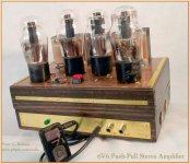
Additional completed amplifier image
Here's another view of the 6V6 / 6AQ5 amp using some early 'coke-bottle' style 6V6G tubes.
I show the typical Mp3 player feed from my Sandisk Sansa Clip player
Here's another view of the 6V6 / 6AQ5 amp using some early 'coke-bottle' style 6V6G tubes.
I show the typical Mp3 player feed from my Sandisk Sansa Clip player
An externally hosted image should be here but it was not working when we last tested it.
Attachments
Last edited:
- Status
- This old topic is closed. If you want to reopen this topic, contact a moderator using the "Report Post" button.
- Home
- Amplifiers
- Tubes / Valves
- 6V6 or 6AQ5 PP integrated amp w/CCS