Yes, a dropper capacitor and a filament string do not care which end is at hot, and which end is at neutral as far as voltage drop and current are concerned.
However, if the tubes can not take 120V x 1.414 = 170V peak from filament to cathode, then it does matter which way the dropper and filaments are wired. So, the filaments need to be at or near the neutral end (or more accurately at the ground end, where the cathodes are).
And, since the amp chassis ground is at neutral, that is another problem.
I have been in electronics manufacturing plants where neutral is 8VAC away from ground.
That is because there is no current in the earth ground (at least not supposed to be significant current). But there is lots of current in the neutral wire, just as much current as in the hot wire. The voltage drop of IxR was 8VAC in this case.
Ground and Neutral are the same voltage at only one point . . . the power panel.
Everywhere else, they are volts apart. Do not join neutral and ground at the power socket, and do not join neutral and ground at the amp.
I have seen smoking wires when an attempt was made to join ground and neutral (saw a 22 gauge wire go up in smoke, when it tried to lower the voltage drop across the 12 gauge neutral wire that was carrying lots of current).
Some hi fi gear does use ground as the reference for input jacks and output jacks.
Now, just try and join an amp that is using Neutral as its "chassis ground" that is the reference for input and output jacks.
I think you can see what happens then.
I did a test of an outlet in the house, and it is only 1.3VAC from ground to neutral. Other outlets may vary.
However, even if it could be very low voltage, if there are any equipment with switchers, or even with 2x line frequency rectifier currents, there will be noisy ground loops. That is because higher frequencies such as rectifier line harmonics and switchers are higher frequencies, and the long wires become quite inductive at these frequencies.
Last edited:
Weird. Usually in a manufacturing plant they'll be using 3 phase, and in that case the neutral shouldn't carry any appreciable current (unless it's high leg delta, but that's a different story).
I've just checked ground to neutral (Apartment building fed by 3PH 120/208V) and it's 223mV.
In a residential setting neutral is tied to ground in the house though, so I'd expect almost no offset.
I've just checked ground to neutral (Apartment building fed by 3PH 120/208V) and it's 223mV.
In a residential setting neutral is tied to ground in the house though, so I'd expect almost no offset.
As the OP apparently has corrected his PSU issue, I think it is time to return to a discussion on his amplifier itself:
You don't really want to use RCA jacks as loudspeaker terminals, do you?
Best regards!
You don't really want to use RCA jacks as loudspeaker terminals, do you?
Best regards!
The 8V difference in Neutral and Ground was caused by unbalanced loads of the 3 phases of power in the manufacturing plant.
It is always a good idea to check power outlets, no matter where.
I once had a vacuum tube aficionado who was living in a trailer. The trailer 2-phase wiring was faulty, and the power was up at about 150V (supposed to be 120V).
I did mis-speak when I said:
"An amplifier with RCA phono input connectors and speaker output connectors is a totally different thing". The missing comma after 'input connectors' led you to believe that I use RCA phono jacks for speaker output connectors. Nothing could be further from the truth.
I use '5 way' binding posts (which work with banana plugs, spade lugs, and wire ends . . . '3 ways only')
How they get '5 ways' is beyond me.
How they get '5 ways' is beyond me.
[1] Banana plug
[2] Pin tip plug
[3] Bare wire
[4] 1/4" ID lug
[5] Alligator clip
I did mis-speak when I said:
"An amplifier with RCA phono input connectors and speaker output connectors is a totally different thing". The missing comma after 'input connectors' led you to believe that I use RCA phono jacks for speaker output connectors. Nothing could be further from the truth.
I wasn't objecting you, but referring to the OP's photographs and schematics instead.
Best regards!
Yeah let's please stop beating the PSU dead horse... thanks. lolAs the OP apparently has corrected his PSU issue, I think it is time to return to a discussion on his amplifier itself:
You don't really want to use RCA jacks as loudspeaker terminals, do you?
Best regards!
Why not use RCA jacks for the speakers?
I have been for years with nothing adverse.... can't even image why not.
... so why do you ask that??
Last edited:
Any new-style home outlet here in the US uses a GFI outlet.Yes, a dropper capacitor and a filament string do not care which end is at hot, and which end is at neutral as far as voltage drop and current are concerned.
However, if the tubes can not take 120V x 1.414 = 170V peak from filament to cathode, then it does matter which way the dropper and filaments are wired. So, the filaments need to be at or near the neutral end (or more accurately at the ground end, where the cathodes are).
And, since the amp chassis ground is at neutral, that is another problem.
I have been in electronics manufacturing plants where neutral is 8VAC away from ground.
That is because there is no current in the earth ground (at least not supposed to be significant current). But there is lots of current in the neutral wire, just as much current as in the hot wire. The voltage drop of IxR was 8VAC in this case.
Ground and Neutral are the same voltage at only one point . . . the power panel.
Everywhere else, they are volts apart. Do not join neutral and ground at the power socket, and do not join neutral and ground at the amp.
I have seen smoking wires when an attempt was made to join ground and neutral (saw a 22 gauge wire go up in smoke, when it tried to lower the voltage drop across the 12 gauge neutral wire that was carrying lots of current).
Some hi fi gear does use ground as the reference for input jacks and output jacks.
Now, just try and join an amp that is using Neutral as its "chassis ground" that is the reference for input and output jacks.
I think you can see what happens then.
I did a test of an outlet in the house, and it is only 1.3VAC from ground to neutral. Other outlets may vary.
However, even if it could be very low voltage, if there are any equipment with switchers, or even with 2x line frequency rectifier currents, there will be noisy ground loops. That is because higher frequencies such as rectifier line harmonics and switchers are higher frequencies, and the long wires become quite inductive at these frequencies.
No self-respecting GFI would ever allow any slight difference in current on the neutral line compared to the hot. The hot and neutral must match or else the GFI shuts off the flow.
So, in fact that's the way the GFI PROTECTS YOU.
It looks for any difference in the amount of current flowing in each path, and there better not be any or it shuts off.
The latest GFIs out there now (in fact) also look to see if Hot and Neutral are reversed and if it detects that they are reversed, it will NOT allow any output.
So... nowadays, with a new GFI in place, you will not be able to ever have hot and neutral even accidentally mis-wired.
Personally, I feel I can comfortably use my amp without an isolation transformer ...only because I KNOW my hot and neutral are properly wired and my GFI insures it.
BTW a GFI will also not allow earth-ground and neutral to be connected together inside the equipment or it shuts off.
Last edited:
I'm not sure I follow the 120v rms or 170v peak potential thing... and how it relates to the cathode potential.Yes, a dropper capacitor and a filament string do not care which end is at hot, and which end is at neutral as far as voltage drop and current are concerned.
However, if the tubes can not take 120V x 1.414 = 170V peak from filament to cathode, then it does matter which way the dropper and filaments are wired. So, the filaments need to be at or near the neutral end (or more accurately at the ground end, where the cathodes are).
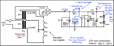
The series filament string terminates at signal-grnd/neutral.
The cathodes are sitting at approx +20vDC w/respect to signal ground.
The four 6.3v filaments are in series on AC, and the RMS voltage (via the dropper cap) at one end of the string is 25.2vAC away from the far end of the string and it reverses each AC cycle.
(The dropper cap is NON-polarized and it can only work on AC so it does NOT ever matter if it is reversed or not)
So where does the 120v rms or 170v peak enter the realm ...esp as it relates to the cathodes which are at +20vDC?
Last edited:
Personally, I feel I can comfortably use my amp without an isolation transformer ...only because I KNOW my hot and neutral are properly wired and my GFI insures it.
Be sure to connect your non-insulated amp only to non-gronded sources then. The GFI will protect you (if correctly installed), but I've seen blown USB DAC and PC audio cards due to fault current flowing between the amp ground and the PC ground. The tube amp will not even notice it: in a similar situation, I once saw a small spark inside the preamp tube as soon as I plugged the RCA cable in the input terminal. The tube was totally fine and undamaged, the PC sound card destroyed. A very small current is enough to damage semiconductors on the source. I would use a insulation transformer just to avoid potential damages. The cost of a 200-300VA toroid transformer is low, and you may even wrap a few extra turns of magnet wire around it to get an improvised filament winding.
Last edited:
Why not use RCA jacks for the speakers?
I have been for years with nothing adverse.... can't even image why not.
... so why do you ask that??
First reason is to avoid confusion between input and output, ot input and output cables, second is the rather tiny contact aerea, especially for the hot pin. RCA jacks just aren't dedicated to carry significant current.
Best regards!
Thanks. Good suggestions.Be sure to connect your non-insulated amp only to non-gronded sources then. The GFI will protect you (if correctly installed), but I've seen blown USB DAC and PC audio cards due to fault current flowing between the amp ground and the PC ground. The tube amp will not even notice it: in a similar situation, I once saw a small spark inside the preamp tube as soon as I plugged the RCA cable in the input terminal. The tube was totally fine and undamaged, the PC sound card destroyed. A very small current is enough to damage semiconductors on the source. I would use a insulation transformer just to avoid potential damages. The cost of a 200-300VA toroid transformer is low, and you may even wrap a few extra turns of magnet wire around it to get an improvised filament winding.
I designed this amp primarily as an Mp3 fed power amp. So my Mp3 device is battery powered.
The GFI would shut off power to the amp if any of the neutral-connected surfaces were to contact earth ground. So I think I'm ok as far as that goes.
I was using a dual-wound 12v power transformer on my 5902 version of this amp.
Attachments
Last edited:
Thanks.First reason is to avoid confusion between input and output, ot input and output cables, second is the rather tiny contact aerea, especially for the hot pin. RCA jacks just aren't dedicated to carry significant current.
Best regards!
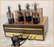
If you look at the front panel you'll notice that the input jack (Mp3) is a completely different type of jack from the two RCA speaker output jacks.
I don't know what the RCA jack current rating is but we're only dealing with the 6V6 PP speaker audio signal here.
How much current do you suppose that might be?
Attachments
Last edited:
Any Waveform:
8 Watts rms into 8 Ohms = 1A rms
Sine Wave:
8 Watts rms into 8 Ohms = 1.414A Peak
For loudspeakers that are anything but 8 Ohms Resistive . . . (almost all loudspeakers are non resistive at most points across the audio band,
and almost all loudspeakers are not constant impedance across the audio band), . . . the numbers are unknown.
Depending on your music waveform, your loudspeakers, and the amplifier gain and maximum output power,
"Your Mileage May Vary".
Last edited:
Thanks...Any Waveform:
8 Watts rms into 8 Ohms = 1A rms
Sine Wave:
8 Watts rms into 8 Ohms = 1.414A Peak
For loudspeakers that are anything but 8 Ohms Resistive . . . (almost all loudspeakers are non resistive at most points across the audio band,
and almost all loudspeakers are not constant impedance across the audio band), . . . the numbers are unknown.
Depending on your music waveform, your loudspeakers, and the amplifier gain and maximum output power,
"Your Mileage May Vary".
So with 8 watts we're not talking about more than an amp or so... right?
I tried to find the exact current-carrying specs for RCA jacks and all I found out there so far, was the general consensus from lots of folks, that RCA jacks can carry quite a bit. At least 3-5 amps to maybe two or more times that because there's such a large metal contact surface area for both contacts (pin & sleeve).
Ref:
What dangers are there putting power through RCA connectors? - Electrical Engineering Stack Exchange -----------------------------------
"I've often used them at about 5A. They get a bit warm towards the higher end but I haven't had one melt (so far). I standardised on using red ones for 5V and yellow for 12V, same as ATX wiring."
"The RCA connector can handle 48v and 3amp. I have this arrangement on a electric bike battery charging circuit. What is important is that the cables used can also handle that current without getting hot enough to melt the insulation. Voltage rating below 48v not a problem "
----------------------------------------------------------------------------
(I'd really rather see a manufacturer's written specification to be certain.)
But .. so far at least, it confirms for me that using the RCA jack, as I am, for speaker-output signals is sound. ( no pun intended) 🙂
If you happen to find an actual manufacturer spec please pass along the link.
Last edited:
- Status
- Not open for further replies.
- Home
- Amplifiers
- Tubes / Valves
- 6V6 or 6AQ5 PP integrated amp w/CCS