Are you 100% that it not something else distorting?
Well I’m not overdriving the Soundcard Interface. I got bitten by that a few months back when modifying a crossover. Severely clipping the test signal results in lots of high order harmonics that messes up the amplitude vs frequency measurements!
The gain of the two output tubes needs to be equal in class aB to get low H distortion without N Fdbk. Either selected/matched tubes or a gain matching pot in the driver section.
The gain of the two output tubes needs to be equal in class aB to get low H distortion without N Fdbk. Either selected/matched tubes or a gain matching pot in the driver section.
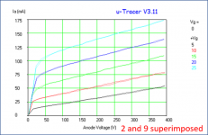
Thanks. Would matched Rg2g1/Rg1, 1.89k/10k Ia vs Va plots do it?
Attachments
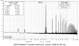
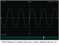
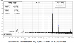
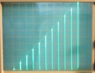
Screen drive mesaurements
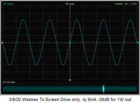
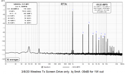
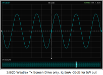
I removed the Rg2g1 resistors. Plots below are:
Less gain of course. At 5W the MOSFET sources are swinging 32V RMS according to the metre on the soundcard interface.
Finally, there's a picture of the test setup.
I removed the Rg2g1 resistors. Plots below are:
- 1W scope
- 1W RTA
- 5W scope
- 5W RTA
- 5W Q1 Source RTA
- 5W Q1 Source RTA
Less gain of course. At 5W the MOSFET sources are swinging 32V RMS according to the metre on the soundcard interface.
Finally, there's a picture of the test setup.
Attachments
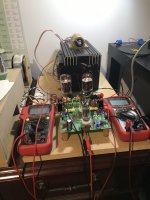
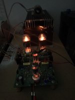
Some quite heavy looking red plate action going on in that photograph!
Whoa I thought! How did I miss that?
Turns out it's a reflection of the red plastic case of the metre in the foreground.
Here's one taken in the dark under the same operating conditions.
Attachments
The 5W scope trace in post 219 looks a lot like gm doubling, I've seen similar looking sinewaves in simulations. Have a read of this tubecad post:
Constant-gm Output stages part two
Also some discussion here where he shows that a perfectly linear output device (as we are trying to achieve with crazy drive) is a poor choice for a class AB output stage:
Class-A? Class-AB? Amplifiers
In simulations of screen drive / crazy drive using a 6DQ5, a 22ohm cathode resistor in parallel with a diode for each output tube reduced distortion quite a bit.
It seems the alternative of biasing the output stage low enough that the transconductance is reduced sufficiently doesn't work so well in practice, as it's a fine line between that and crossover distortion.
The 5W scope trace in post 219 looks a lot like gm doubling, I've seen similar looking sinewaves in simulations. Have a read of this tubecad post:
Constant-gm Output stages part two
Also some discussion here where he shows that a perfectly linear output device (as we are trying to achieve with crazy drive) is a poor choice for a class AB output stage:
Class-A? Class-AB? Amplifiers
In simulations of screen drive / crazy drive using a 6DQ5, a 22ohm cathode resistor in parallel with a diode for each output tube reduced distortion quite a bit.
It seems the alternative of biasing the output stage low enough that the transconductance is reduced sufficiently doesn't work so well in practice, as it's a fine line between that and crossover distortion.
Thanks for those links. I've never really understood gm doubling before but I do now.
I spent several years tinkering with screen drive and crazy / dual (G1 + G2) drive. I made several test amps including some that were quite powerful, however none ever turned into something that I wanted to make into a pretty case and put in my system. Part of this was because my work room / listening room / lab / recording studio was about 100 square feet and rather full, and my work schedule did not offer much build time.
These experiments did yield some test amps that lived in my system for a day or two up to a month or two. From those I can offer some observations.
Screen drive or G1 + G2 drive both create an amplifier with a rather high output impedance, equal to, or sometimes higher than pure pentode.
All OPT's are imperfect. Some are much more imperfect than others. Things like low primary inductance, leakage inductance, and stray capacitance are far less of an issue when the source (output tubes) impedance is low. Think of the tube as a perfect signal source with a resistor in series with it's output and a "mess" of unwanted capacitors and inductors on the other side of the resistor. The lower that resistor is, the less of an effect the "mess" will have on the signal.
Feedback can be used to "clean up the mess" by lowering the amp's output impedance, but it only goes so far before creating other issues.
Driving a pentode via G2, or G1 + G2 can result in blown tubes in high power situations. I literally blasted the screen grid out of a few sweep tubes before figuring out the mechanism. This happens under constant sine wave operation at very high power. Here G2 is swinging from slightly negative to a couple hundred volts positive. The grid eats a large percentage of the cathode current when the plate is pulled down to a low voltage (under 20 volts in a big sweep tube) and the grid is at +250 volts. The grid wires can get hot, glowing red hot. On the next half cycle the tube goes toward cutoff, where that glowing grid is near zero volts while the plate is somewhere north of 1000 volts. That glowing grid can emit enough electrons that travel to the plate to cause an electron stream leading to a catastrophic tube arc.
G1 + G2 drive can reduce the total grid voltage requirements reducing this possibility, but I did make it happen on a dual drive amp. Note that the likelihood of such an arc is very low in an amp playing music, and I only saw it happen in sine wave testing near clipping.
Screen drive and G1 + G2 drive seem to bring out those little tube to tube variations that drive up the higher order harmonics. Careful tweaking of the DC and AC operating points can reduce these, but they may reoccur as the tubes age.
I spent several years tinkering with screen drive and G1 + G2 drive in a setup similar to DCH53's, Universal Driver board, three adjustable power supplies, and several OPT's. There have been several tests with small tubes like the 6W6 all the way up to 6LW6, 4D32 and 7403. In all cases I was able to get equal or better output performance in conventional G1 drive. Screen drive excels in two areas, a possible 5 to 10% efficiency improvement, and a lower idle current for the same THD. The lower idle current may be responsible for the efficiency improvement since the improvement drops off as you approach clipping.
The primary reason for chasing screen and dual drive was to eliminate the multiple complex power supplies in the typical tube amp, and to allow for triode like operation in a TV sweep tube where the max G2 voltage spec is quite low.
Several years ago I decided to back up and make a "universal" output board with one or two mosfets on every electrode except the plate. The complementary outputs from the driver board allowed me to apply in phase or out of phase drive to any element on the tube with any DC offset. This work is finally paying off with cathode drive.
I have two working amp designs and passed the 300 watts from a single pair of 36LW6 tubes last night. It blew up trying to make 350. I share these results and the circuit about a month ago, and several people have come up with improvements. I currently think it is the way to go forward, but it's still early. Some links:
If UNSET and the RCA50W Had a Baby
UNSET is coming?
https://www.diyaudio.com/forums/tub...sing-mosfet-ultralinear-feed.html#post6267790
Would matched Rg2g1/Rg1, 1.89k/10k Ia vs Va plots do it?
Matched resistors alone would not guarantee matched gains (depends on gm), but the tube plots you show look like they are well matched.
Trying to get low distortion without any N Fdbk also places heavy requirements on the OT used. The two P-P sides need to have equal winding resistance (and of course equal turns ratios). Adding a series resistance into one P-P winding side can be done to equalize the winding resistances.
Then there is distributed capacitance in the two winding sides. Generally that requires the use of split bobbin windings, with identical builds on each side. But one could maybe put a variable cap across one winding side and try to equalize the even Harmonic response. Or, maybe try to get equal winding resonance frequencies in isolation.
Another problem could be from the Rg2g1 resistors being non-linear at high voltages if they are thin film types. Can either use composition resistors and/or series equivalent resistors to reduce the voltage across each resistor.
The scope curves shown earlier look like plain old 2nd or 3rd H distortion is rampant. This may be some problem with the drive signals or splitting. Crossover distortion would show up as higher harmonics, especially with low signal levels.
Crazy drive reverts to just g1 drive at very low drive signal levels, since g1 is no longer current constrained (through Rg2g1). This means that optimum idle current should be much lower than normal g1 drive. It could be very touchy to set right though, and to maintain.
Below are some Vin to Iout curves done for 26LX6 (similar to 6HJ5) for high current range and low current range. You can see the reversion to a g1 drive shape at low signal levels. The crossover conduction overlap would only need to occur in the low current curved region.
Attachments
Last edited:
I can't help but notice that crazy drive curves look a lot like high-impedance transmitter triode curves.
About transformers, I will add the following: Driving a audio trafo with low impedance we will battle problemas like parasitic capacitance and primary inductance, but we lose against leakage inductance. Some people (like Rod Elliott) says that triodes have more IMD than pentodes, and he right, if we consider practical transformers in class AB operation, transitioning to class B. The leakage inductance provokes a huge increase of IMD in this region (and HF HD distortion increases too), but barely a increase of single tone low frequency THD in certain cases. Solution is to use class A only, or mitigate a little using pentode/high impedance output and feedback from secondary.Matched resistors alone would not guarantee matched gains (depends on gm), but the tube plots you show look like they are well matched.
Trying to get low distortion without any N Fdbk also places heavy requirements on the OT used. The two P-P sides need to have equal winding resistance (and of course equal turns ratios). Adding a series resistance into one P-P winding side can be done to equalize the winding resistances.
Then there is distributed capacitance in the two winding sides. Generally that requires the use of split bobbin windings, with identical builds on each side. But one could maybe put a variable cap across one winding side and try to equalize the even Harmonic response. Or, maybe try to get equal winding resonance frequencies in isolation.
Another problem could be from the Rg2g1 resistors being non-linear at high voltages if they are thin film types. Can either use composition resistors and/or series equivalent resistors to reduce the voltage across each resistor.
The scope curves shown earlier look like plain old 2nd or 3rd H distortion is rampant. This may be some problem with the drive signals or splitting. Crossover distortion would show up as higher harmonics, especially with low signal levels.
Crazy drive reverts to just g1 drive at very low drive signal levels, since g1 is no longer current constrained (through Rg2g1). This means that optimum idle current should be much lower than normal g1 drive. It could be very touchy to set right though, and to maintain.
Below are some Vin to Iout curves done for 26LX6 (similar to 6HJ5) for high current range and low current range. You can see the reversion to a g1 drive shape at low signal levels. The crossover conduction overlap would only need to occur in the low current curved region.
I "discovered" this well documented and explained phenomenon when I tested a Ge emitter follower amplifier (low impedance drive), that having 0.01% THD max at 1kHz-1W (is not a typo), but when it enter in class B with IMD testing, the IMD jumps to almost 5%, from initial <0.1%.
Last edited:
Then there is distributed capacitance in the two winding sides. Generally that requires the use of split bobbin windings, with identical builds on each side. But one could maybe put a variable cap across one winding side and try to equalize the even Harmonic response. Or, maybe try to get equal winding resonance frequencies in isolation.
I found the unequal C to the core was a problem in Hammond 1600 & 125 Series OPT's back around 1960. Typical was a difference of 150-200 pF for that group at that time. Don't expect it to be much better now, many of the primaries are serially wound. I set the test up as a bridge, my notes are still somewhere in the pile here.
For the build of Crowhurst's Twin Coupled Amp, the capacity unbalance was corrected by reversing both primary & secondary connexions. The circuit without that fix had poor performance on any test.
As already noted, the difference of resistance in the two sides of the primary wdg can be fixed by a resister. Not a good way to go, but works. Usually don't need that.🙂
True, is not very common to find a PP trafo with rdc, LL (leakage inductance) and parasitic capacitance equal at both sides
I made some toroidal trafos with two equal hemispheres (geometrically divided), and if winding is not perfect distributed, and pressure on windings and insulation layers are not equal at all sides and levels, this not affect the rdc very much (is very well matched), but LL and capacitance can differ a lot for each side, even 2:1 ratio, especially for LL
For sure the poor parasitics balance can saturate the core even at HF in a low bias PP amp due to unequal net DC current flowing resulting from this distortion.
McIntosh preferred the Unity Coupling method just because of that geometrically induced problems.
One more thing...
Compensating externally the rdc may worsens the HF behaviour; due to interaction with the parasitic capacitance and LL
Whoa I thought! How did I miss that?
Turns out it's a reflection of the red plastic case of the metre in the foreground.
Here's one taken in the dark under the same operating conditions.
Hahaha....need to get my eyes checked!
Thank-you all for the detailed explanations. I am aware that this old Westrex OPT I'm using has serious leakage inductance issues.
A couple of Toroidy EL84 8k output toroids arrived yesterday. I'll try one of those with a 4Ω load.
A couple of Toroidy EL84 8k output toroids arrived yesterday. I'll try one of those with a 4Ω load.
Thanks George. I'm following the UNSET and related threads with great interest.
There's something about the synergy between the old and the new with a large dose of ingenuity thrown in to expand the boundaries of what's possible that I find very interesting.
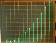
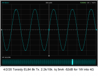
Toroidal OPT measurements
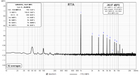
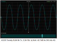
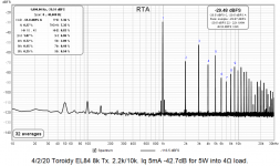
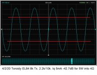
I tried an 8K EL84 OPT and attached a 4Ω load.
5W performance is worse than with the old Westrex OPT.
Based on an earlier observation I think there's evidence of gm doubling in the 5W scope shot.
Time to put finding the perfect output stage for my Universal Driver Boards on the back burner. Ultimate aim is around 100W to replace my existing 135W into 8Ω solid-state bass amp in my tri-amped system. Low output impedance/decent damping factor is important so crazy-drive probably wouldn't be appropriate anyway.
Other projects await....
Attachments
perfect output stage for my Universal Driver Boards
They can drive nearly anything, so there are too many choices. I spent nearly a year trying something different every few days, from tiny (6W6, 6GF5, and even 50C5 tubes from an old radio) to big, (6LW6 sweep tubes and 4D32 transmitter tubes).
The only one that I (and a couple others) started building into a complete amp is an old school triode wired quartet of 6550's or KT88's. They are good for about 75 WPC into a 3300 ohm load on 450 volts. The final rack mounted amp is about 1/3 finished. The prototype test setup is seen here.
75 watt per channel triode mode tube amp prototype - YouTube
I've noticed on your scope shots the slight bend in the sine wave as it passes thru a certain level. That is caused by the load change on the driver circuit as it is required to go from one grid to driving both, not your OPT.
Need to isolate the output stage into something simpler. With any NFB unhooked look at the output stage grid drive. Think you will find that is the origin of part of the problem.🙂
Used to be easy to see, this kind of circuit was transformer driven. A sampling resister could be put at the low end of the IT, a scope could indicate the grid current bump.
Attachments
- Home
- Amplifiers
- Tubes / Valves
- More Ruminations on Screen Drive/Crazy Drive