Hello folks!
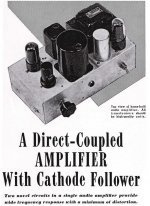
Currently I'd like to undertake the construction of a small direct-coupled amplifier (designed I suppose in 1949) capable according to it's designer of wide frequency response with small amount of components and with the minimum distortion (I suppose less than 2%?).
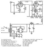
• As T2 - Power transformer, I found the 373BX by Hammond (http://www.hammondmfg.com/pdf/EDB373BX.pdf)
• As CH1 - Filter choke, I found the 157J by Hammond (Hammond Mfg. - D.C. Filter Chokes - (153 - 159 Series))
• As T1 - Output transformer, I found the 1629SEA (Hammond Mfg. - "Classic" Single Ended Tube Output Transformers - (1627 - 1642 Series))
Please see the attachments.
As regards these components I have some doubt about the CH1 (I did not found any perfect match). Do you have some suggestion ? Are the other components suitable for this amp?
Moreover I'd like to add a tone control, would you be so kind to explain me precisely how I can made this modification to the circuit?
And finally have you some other suggestion in building this little amp?
Thank you and have a nice Christmas!
Currently I'd like to undertake the construction of a small direct-coupled amplifier (designed I suppose in 1949) capable according to it's designer of wide frequency response with small amount of components and with the minimum distortion (I suppose less than 2%?).
• As T2 - Power transformer, I found the 373BX by Hammond (http://www.hammondmfg.com/pdf/EDB373BX.pdf)
• As CH1 - Filter choke, I found the 157J by Hammond (Hammond Mfg. - D.C. Filter Chokes - (153 - 159 Series))
• As T1 - Output transformer, I found the 1629SEA (Hammond Mfg. - "Classic" Single Ended Tube Output Transformers - (1627 - 1642 Series))
Please see the attachments.
As regards these components I have some doubt about the CH1 (I did not found any perfect match). Do you have some suggestion ? Are the other components suitable for this amp?
Moreover I'd like to add a tone control, would you be so kind to explain me precisely how I can made this modification to the circuit?
And finally have you some other suggestion in building this little amp?
Thank you and have a nice Christmas!
Attachments
Filter choke, I found the 157J by Hammond
I'd use the 157L choke instead.
This is the kind of amp that might be best built on a piece of plywood. Getting output stage current dialed in properly will require adjustability somewhere, as your output transformer will not have the same DCR as what that amp was designed for.
Tone controls aren't going to be easy to add to this amp, you'll need more gain stages to drive them.
Tone controls aren't going to be easy to add to this amp, you'll need more gain stages to drive them.
I'd use the 157L choke instead.
Thank you for the reply and for the suggestion.
I didn't choose the 157L because I wasn't sure if a greater inductance would decreased the voltage under 335V. May I ask you why you prefer this one?
This is the kind of amp that might be best built on a piece of plywood. Getting output stage current dialed in properly will require adjustability somewhere, as your output transformer will not have the same DCR as what that amp was designed for.
Tone controls aren't going to be easy to add to this amp, you'll need more gain stages to drive them.
Thank you too for the reply and the suggestions. First of all is not metal chassis advisable and why? Secondly how can I resolve the problem with the output transformer? Can you please provide me a suitable one?
Thanks
I didn't choose the 157L because I wasn't sure if a greater inductance would decreased the voltage under 335V. May I ask you why you prefer this one?
The 157J should work ok also, but has less inductance. There seems to be plenty of B+ voltage,
since 50mA x 429R is still only around 20V drop.
The schematic specifies the output transformer to have 6k/8R windings, with 650R primary resistance, and 50ma DC handling. That leaves the Hammond 1629SEA as the best choice from their offerings, as you found. Only 11 pounds.
Sorry, be patient but I'm still novice in the DiY field of tube amp.
Isn't specified 6K/8R (6000ohm input, 8ohm output) with 250ohm of d.c. primary resistance rather than 650ohm of d.c. primary resistance?
Secondly, a greater impedance (in this case 6500ohm) how possibly affects the operation of the amplifier (i.e. more distortion?)
I vote to build it on a piece of plywood so that you can easily dial in any changes that you may need to make.
Thank you Audiowize for the clarification. See, this will be my second diy amp so as said I'm still a novice.. what kind of changes can occur with an amp such the one I'm intended to built? Seems that it is not a good circuit..
Last edited:
Isn't specified 6K/8R (6000ohm input, 8ohm output) with 250ohm of d.c. primary resistance rather than 650ohm
of d.c. primary resistance? Secondly, a greater impedance (in this case 6500ohm) how possibly affects the operation of the
amplifier (i.e. more distortion?)
Yes, 250R, sorry for the typo. Generally, mismatching the primary impedance can affect power, distortion, and bandwidth. Here, the difference is small and shouldn't make any difference.
Thanks for the clarification!
I'm also concerning about primary resistance. How much it should be for the 1629SEA? And an eventual variation from the specified valued (250ohm) what kind of effects can occurs?
Here this value determines the grid bias for the 6v6 so it is necessary increase or decrease the real 1629SEA value maybe adding in series or in parallel a resistor?
In case do you know where (online) I can find a more adequate amplifier so I can be sure?
At first look at the schematic I was skeptical about the damping factor.
The bottom of T1 has a fairly high impedance path to ground.
1355 Ohms to ground; & >100,000 to the right.
Apparently, the path from the bottom of T1 to the screen of the input tube is to give negative feedback. That will reduce distortion.
But the high resistance also reduces damping factor.
A second look shows the following:
The 6V6 GM is about 4000uMhos (250 Ohms).
The un-fedback damping factor is about 6000 Ohm primary driven by 1605 Ohms.
6000/1605. The un-fedback damping factor is 3.74, pretty good. The negative feedback to the screen should make it a little higher.
I was surprised when I took the closer look.
Anybody else see an error in my approximation?
Member
Joined 2009
Paid Member
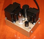
Cool project - I love the whole retro look. I made a spud amp ( http://www.diyaudio.com/forums/tubes-valves/280167-yukon-gold-spud-amp.html#post4460585 ) on a small metal chasis with a see-through perspex bottom panel and it's a great conversation piece plus to sounds ok too. It is crowded inside the little box, so I prototyped mine on a large metal experimental chasis first to get the part values to my liking and then I re-built it on a small box (see pic).And finally have you some other suggestion in building this little amp?
I tried using small transformers to keep the size and weight down. I don't think those large Hammond output transformers are necessary here. I'd suggest one of the small power Edcor output transformers instead and you can paint if black if you want to like I did (power supply choke is inside the box).
Hot resistors should have some way to stay cool, possibly bolted to the chassis if you can do that safely. Thermal considerations would suggest solid state rectifier, a personal choice of course.
Attachments
Last edited:
Thanks for the clarification!
I'm also concerning about primary resistance. How much it should be for the 1629SEA?
Contact Hammond and ask them, i'm sure they'll be helpful.
- Status
- This old topic is closed. If you want to reopen this topic, contact a moderator using the "Report Post" button.
- Home
- Amplifiers
- Tubes / Valves
- Direct-Coupled Amplifier with Cathode Follower by R.H. Bates