The declared wattage of this amp is around 4.5W
4.5W at the speaker means 164V RMS at the primary of the output transformer. There is something not adding up here
I think those are reasonably close. Close enough to be able to easily tweak the circuit into proper operation.
The files are the circuit file (.asc) and include files which model the tubes. These can be used with he spice simulation package LTSpice.
Unfortunately these are for windows.
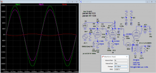
I constructed a model of the amplifier circuit to see how it behaved with models of the tubes.
Unfortunately these are for windows.
I constructed a model of the amplifier circuit to see how it behaved with models of the tubes.
audiowize, that corresponds to 4V peak at the speaker. I didn't get that when running the simulation, I clipped before that.
In addition, I agree. 164Vrms is 239V peak. Divided by 4V peak is a turns ratio of almost 60:1. a 6K to 8 transformer has a turns ratio of Sqrt6000/8 = 27.4:1
Something is not adding up.
In addition, I agree. 164Vrms is 239V peak. Divided by 4V peak is a turns ratio of almost 60:1. a 6K to 8 transformer has a turns ratio of Sqrt6000/8 = 27.4:1
Something is not adding up.
HMV130 the article states that the direct coupled circuit depends on the 250 ohms DCR of the output transformer, the one you linked is only 187 ohms. A better choice is the Edcor GXSE10-8K which is 255 ohms EDCOR - GXSE10-8K. The circuit will be out of balance if it is too far off. This output transformer is 8K not 6K so output power will be a little less, but distortion will be less also.
250-187=63 ohms
R Init =R3 + R5 + Rxfmt = 1000+ 355 +250 = 1605
R new = 1000+ 355 + 187 = 1542
Bias resistor chain variance = (1605-1542) / 1605 = .03925.
This is well below the tolerance of resistors used at that time (5 and 10 percent) and should not be an issue.
the simulation only shows a 1ma shift due to the difference in the transformer resistance. It is swamped by the other components.
It is too bad the author of the article doesn't list the model or DCR of the 12H filter choke. He does say in the article there is a 15volt drop across the filter choke. If you use the calculator on this page, Dropping Resistor Calculator | GTSparkplugs enter 335V as the needed voltage, and add enter 350 volts as the starting voltage (for the 15V drop), and enter .053 as the current draw it calculates a resistance of 283 ohms. The Hammond 159M is the closest match, it has a DCR of 256 ohms, 15H would give you a little more filtering which is beneficial.
Just over 3 watts using 6n6 driver I sim before. It'll need about 125V RMS on the primary of a 4k OT to give 5V RMS out on 8 ohms load. So confirmed it's the driver needs rework (how?) since it is unable to drive the output stage to full output or only 1/4 watt out as per original schematic.
Attachments
It might be worth contacting Edcor and ask if the the Edcor GXSE10-8K can be made with a 6K primary while maintaining the 255 ohms DCR, possibly for a small fee
Last edited:
It looks to me like direct coupling buys you pretty much nothing here and adds a lot of complexity. If it were me, I would build the thing cap-coupled.
I'd save direct coupling for some situation were I am concerned about extra phase shifts in out-of-band frequencies or something, unless you are just looking for a challenge.
I'd save direct coupling for some situation were I am concerned about extra phase shifts in out-of-band frequencies or something, unless you are just looking for a challenge.
First of all I wan to thank you all guys for the support.
Secondly I have not clear what are the variables that we must not change in this circuit with regards to the output transformer in order to have the minimum distortion and the maximum power of output.
We have a primary input impedance of 6000 or 5000 ohm (which seems not correct considering the voltage drops calculations, right?) and primary input DCR of 250 ohm (which determine the current at the grid of the 6v6).
For the best functioning (the minimum distortion and the maximum power of output) we should modify the primary input impedance (with which effects?) or we should modify the primary input DCR (with which effects?)
Finally is not the best solution keep an input impedance of 6000 or 5000 ohm and primary input DCR of 250 ohm by adding some resistor coupled with a capacitor thus according to a chosen output transformer?
HMV130 the article states that the direct coupled circuit depends on the 250 ohms DCR of the output transformer, the one you linked is only 187 ohms. A better choice is the Edcor GXSE10-8K which is 255 ohms EDCOR - GXSE10-8K. The circuit will be out of balance if it is too far off. This output transformer is 8K not 6K so output power will be a little less, but distortion will be less also.
250-187=63 ohms
R Init =R3 + R5 + Rxfmt = 1000+ 355 +250 = 1605
R new = 1000+ 355 + 187 = 1542
Bias resistor chain variance = (1605-1542) / 1605 = .03925.
This is well below the tolerance of resistors used at that time (5 and 10 percent) and should not be an issue.
the simulation only shows a 1ma shift due to the difference in the transformer resistance. It is swamped by the other components.
Secondly I have not clear what are the variables that we must not change in this circuit with regards to the output transformer in order to have the minimum distortion and the maximum power of output.
We have a primary input impedance of 6000 or 5000 ohm (which seems not correct considering the voltage drops calculations, right?) and primary input DCR of 250 ohm (which determine the current at the grid of the 6v6).
For the best functioning (the minimum distortion and the maximum power of output) we should modify the primary input impedance (with which effects?) or we should modify the primary input DCR (with which effects?)
It looks to me like direct coupling buys you pretty much nothing here and adds a lot of complexity. If it were me, I would build the thing cap-coupled.
I'd save direct coupling for some situation were I am concerned about extra phase shifts in out-of-band frequencies or something, unless you are just looking for a challenge.
Finally is not the best solution keep an input impedance of 6000 or 5000 ohm and primary input DCR of 250 ohm by adding some resistor coupled with a capacitor thus according to a chosen output transformer?
Last edited:
It is too bad the author of the article doesn't list the model or DCR of the 12H filter choke. He does say in the article there is a 15volt drop across the filter choke. If you use the calculator on this page, Dropping Resistor Calculator | GTSparkplugs enter 335V as the needed voltage, and add enter 350 volts as the starting voltage (for the 15V drop), and enter .053 as the current draw it calculates a resistance of 283 ohms. The Hammond 159M is the closest match, it has a DCR of 256 ohms, 15H would give you a little more filtering which is beneficial.
Thank you for the clarification. Now I'm bit confused.. Could the calculation of the voltage drops be inaccurate?
4.5W at the speaker means 164V RMS at the primary of the output transformer. There is something not adding up here
audiowize, that corresponds to 4V peak at the speaker. I didn't get that when running the simulation, I clipped before that.
In addition, I agree. 164Vrms is 239V peak. Divided by 4V peak is a turns ratio of almost 60:1. a 6K to 8 transformer has a turns ratio of Sqrt6000/8 = 27.4:1
Something is not adding up.
Finally is not the best solution keep an input impedance of 6000 or 5000 ohm and primary input DCR of 250 ohm by adding some resistor coupled with a capacitor thus according to a chosen output transformer?
You can find a transformer to make it all work out but I think it is worth taking a step back and ask what the direct coupling is buying you. I don't think it buys anything significant.
Plus, this design is fatally flawed IMHO. It uses a cathode follower, which provides an awesome, low impedance drive to the speaker. However, it ruins this low output impedance by not connecting the other side of the OT primary to AC ground. Now there is cathode degeneration as well which raises output impedance. Much better results (lower Zout, wider frequency response) could be had by using a more conventional architecture, but keeping the cathode follower output stage idea.
But if you like this design, don't let me dissuade you from building it. It could be a fun learning experience making it all work out. I'm just trying to point out that the author of the schematic states his goals and then makes some fairly big compromises on those goals for the sake of direct coupling, which doesn't seem to provide any real tangible benefits in this application other than it looks cool.
As previously said, I'm quite a newbie in this field, I do not need so much power (I already have a 15W Heatkit tube amp which I use at less than half of its potential) but I do need a very wide frequency response and due to my knowledge a simple circuit.
So, in case can you provide me a more suitable alternative to this circuit (I prefer 6 or 5V heater tubes due to the fact I have some that I can use and I have already a 325-0-325 power transformer etc.)? Or would you be so kind to help me in modifying this schematic in order to improve it where Mr. Bates "failed"?
Last edited:
As previously said, I'm quite a newbie in this field, I do not need so much power (I already have a 15W Heatkit tube amp which I use at less than half of its potential) but I do need a very wide frequency response and due to my knowledge a simple circuit.
So, in case can you provide me a more suitable alternative to this circuit (I prefer 6 or 5V heater tubes due to the fact I have some that I can use also have already a 325-0-325 power transformer etc.)? Or would you be so kind to help me in modifying this schematic in order to improve it where Mr. Bates "failed"?
I'd be happy to draw something up for you. Can you start by listing as many design goals as you can? (desired power, zout, circuit and power supply complexity etc.)
I read through this design not too long ago and came up with the same questions that audiowize and TheGimp have.
With a 6k primary impedance and 4.5W output we need a peak-to-peak voltage swing on the primary of:
sqrt(6,000 x 8 x 4.5) = 460V
The 6SJ7 is resistor loaded (100k) with a B+ of 250V. It can swing right down to 0V on the anode, so call it 250V peak-to-peak (though it looks like the bias point wouldn't allow it).
The output looks to me like a transformer coupled/loaded cathode follower. So it will provide unity gain. 250V ptp into a 6k primary nets just over a watt.
Am I missing something?
Last edited:
Am I missing something?
I don't think so.
Also, with a 6V6 (triode-connected) with 250V across it at idle, I think it is optimistic to think you can swing more than 300Vpk-pk into the transformer primary with a theoretically perfect and limitless driver. That would give you ~1.8W max undistorted.
I'm not even sure it is possible to get 4.5W out at these conditions even if the output is a square wave. I think the author fudged the numbers here or made a mistake.
HMV130, one issue I see with this is the author did not publish whether he actually measured the amplifier to verify all its operating points, nor do we seem to be able to find anyone who has actually built this design and measured it, so no one has confirmed. The author did build and use it, but it is unknown how close it comes to its design goals, and other readers have posted questions on its design. It might be better to build an established design. I did do a PSUDII simulation on the power supply using the Hammond 373BX transformer and the Hammond 159M choke (15H 256 ohms) and it produces a nice 338V B+ supply using 20uF capacitors. How sensitive are your speakers, how much power do they really need? An output transformer with a 5K primary will have more power than one with an 8K primary but also more distortion. If you have very sensitive speakers then an 8K output transformer will have less power but also less distortion. If this amp actually produces the stated 4.5 watts it may need speakers around 93dB sensitivity or better, if it doesn't quite achieve that, then maybe closer to 96dB is needed. If you have a 325-0-325V transformer on hand, then the first capacitor needs to be a 30uF cap instead of 20uF, and the choke needs to have a lower DCR closer to 100 ohms or less.
I'd be happy to draw something up for you. Can you start by listing as many design goals as you can? (desired power, zout, circuit and power supply complexity etc.)
First of all I want to thank you for being so helpful.
Well, I do not need more than 15W I suppose, something around 8 to 10W is already good.
I'm looking for a simple constructed circuit and without many components (i.e maybe single ended is preferred rather than push pull etc.) but at the same time a very effective one that can provide me hi-fidelity (the minimum distortion - less than 1.5%) and a wide frequency response (as I said power is not the goal).
If possible a volume control and a tone control (for the latter is preferred resistance and capacity circuit).
I do not have preferences for circuit topology but I do have preferences as I said with the regards to the tubes (6V and 5V heater tubes - I already have 6SL7GT, 6J5, 5Y3GT, 6V6GT, 6X5GT etc.).
Moreover for the input stage it needs to be capable of receiving input from a magnetic pick-up (average input voltage).
As for the power supply I have a spare 325-0-325V @ 120mA, 5V @ 2A, 6.3-0-6.3 @ 2A power transformer (otherwise I can buy a new one). I also have a 20H e 50mA spare filter choke. Preferred full-wave tube rectifier using a 5Y3GT or a 6X5GT.
Fuse and pilot light but I can add them easily.
That is all. Hope that indications are as much comprehensive as possible.
Thank you again.
HMV130, one issue I see with this is the author did not publish whether he actually measured the amplifier to verify all its operating points, nor do we seem to be able to find anyone who has actually built this design and measured it, so no one has confirmed. The author did build and use it, but it is unknown how close it comes to its design goals, and other readers have posted questions on its design. It might be better to build an established design. I did do a PSUDII simulation on the power supply using the Hammond 373BX transformer and the Hammond 159M choke (15H 256 ohms) and it produces a nice 338V B+ supply using 20uF capacitors. How sensitive are your speakers, how much power do they really need? An output transformer with a 5K primary will have more power than one with an 8K primary but also more distortion. If you have very sensitive speakers then an 8K output transformer will have less power but also less distortion. If this amp actually produces the stated 4.5 watts it may need speakers around 93dB sensitivity or better, if it doesn't quite achieve that, then maybe closer to 96dB is needed. If you have a 325-0-325V transformer on hand, then the first capacitor needs to be a 30uF cap instead of 20uF, and the choke needs to have a lower DCR closer to 100 ohms or less.
Thank you for summing up all the uncertainties. I think is better not undertake its construction considering what I'm looking for. As regard the 325-0-325V power transformer unfortunately It has less amperage than the required one (6.3 @ 2A, 5V @ 2A). The speaker that I use is a Celestial g-10 vintage.
- Status
- Not open for further replies.
- Home
- Amplifiers
- Tubes / Valves
- Direct-Coupled Amplifier with Cathode Follower by R.H. Bates