I would like to share this Mu follower analysis as there are very few to details of inner working of the circuit, I have to come up with one, not quite certain it is corrected so comments are appreciated.
Attachments
-
 Mu Follower Analysis.png188.4 KB · Views: 842
 -
 Mu Follower Analysis-1.png199.1 KB · Views: 802
 -
 Mu Follower Analysis-2.png204.8 KB · Views: 737
 -
 Mu Follower Analysis-3.png198 KB · Views: 705
 -
 Mu Follower Analysis-4.png199.5 KB · Views: 667
 -
 Mu Follower Analysis-5.png196.4 KB · Views: 271
 -
 Mu Follower Analysis-6.png196.3 KB · Views: 389
 -
Mu Follower Analysis.asc4.6 KB · Views: 110

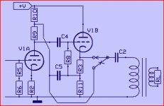
In your last schematic V1A doesn't even have an anode supply 😱
By drawing the thing somewhat different it looks more familiar
Mona
Yes similar, thank you for correction, thank goodness I'm not alone after all.
Attachments

Last edited:
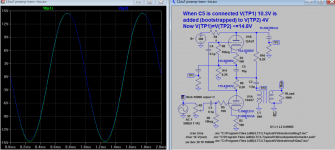
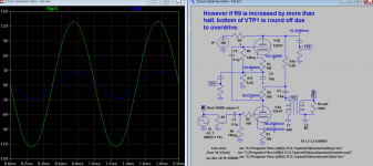
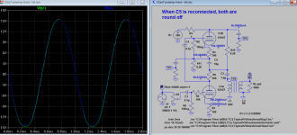
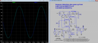
Other than to allow R10 to set the operating point of the lower tube, what is the point of C5?
If direct coupled both circuit, both operating points are upset, and distortion. Nice to do away without it, is it affecting the analysis? I hope not.

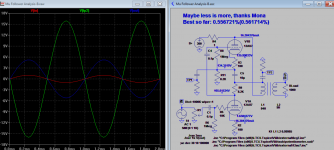
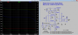
How about less hardware 🙁 Perhaps less is more 😀
Mona
That is indeed is much better than before, thank Mona, let's continue to look for more, for those reader who are already satisfied with analysis maybe can start to build one and let us know how it sounds compared with original. I expect it should be better since there are actually 2 circuits, and I can see they operation need not affect each other.
Attachments
Last edited:
I am a bit confused since these circuits are not exactly what I would call mu followers. If I understand the original post, the idea is to break the mu follower down into its constituent parts and analyze the results. But, the result of doing this doesn't look like a true mu follower. Instead, it looks like a resistor-loaded triode stage feeding a cathode follower. The key feature of a mu follower (that the top triode tries to act like a CCS) looks to be missing from these circuits. Perhaps I am missing something?
The Valve Wizard -Mu Follower
http://www.fetaudio.com/wp-content/uploads/2003/09/Mu-Stage.pdf
The Valve Wizard -Mu Follower
http://www.fetaudio.com/wp-content/uploads/2003/09/Mu-Stage.pdf
I am a bit confused since these circuits are not exactly what I would call mu followers. If I understand the original post, the idea is to break the mu follower down into its constituent parts and analyze the results. But, the result of doing this doesn't look like a true mu follower. Instead, it looks like a resistor-loaded triode stage feeding a cathode follower. The key feature of a mu follower (that the top triode tries to act like a CCS) looks to be missing from these circuits. Perhaps I am missing something?
The Valve Wizard -Mu Follower
http://www.fetaudio.com/wp-content/uploads/2003/09/Mu-Stage.pdf
It's not the Mu follower, and not looks like a resistor-loaded triode stage feeding a cathode follower because of bootstrap. Because it appeared working just like Mu follower for those who dislike original Mu here have a alternative circuit and to compared with. It's a by-product of analysis, that is good thing to happen. I'll find a way to further analyst it, thank you for your helps.
Edit: There is a cathode coupled mu follower http://www.tubecad.com/2009/10/blog0173.htm
Maybe this is it?
Last edited:
That's not a mu-follower, it is a cathode-follower coupled to another cathode follower. It has unity gain.Edit: There is a cathode coupled mu follower SRPP+ All-in-One & Mu Followers
Maybe this is it?
So is this thread supposed to be an analysis of the mu-follower (in which case I might expect to see some algebra), or a groping towards some understanding of how it works or a discussion about circuits which are not mu-followers?
The mu-follower and the common cathode followed by cathode follower with bootstrapping are almost the same circuit for AC purposes. You can analyse one then use the analysis for the other one.
The 'load is almost a CCS' of the mu-follower and the bootstrapping of the gain+CF version do the same thing in the same way: they increase the impedance seen by the first anode and so boost gain and reduce distortion. They also significantly raise the output impedance from what a plain CF would provide.
It does seem like thread title is a bit mis-leading... and what's with all the sims? Some of us like to see the equations...😀So is this thread supposed to be an analysis of the mu-follower (in which case I might expect to see some algebra), or a groping towards some understanding of how it works or a discussion about circuits which are not mu-followers?
Btw, in a µ-follower, you need to bypass the cathode resistor of the bottom tube or the output impedance goes up (and so does distortion a bit iirc).
I found the TubeCad articles, it describes just the thing, no maths so do not worry.
cathode-follower output stage design part-3
DF96
So DF96 please update after when you read it:
"They also significantly raise the output impedance from what a plain CF would provide."
cathode-follower output stage design part-3
DF96
So DF96 please update after when you read it:
"They also significantly raise the output impedance from what a plain CF would provide."
Btw, in a µ-follower, you need to bypass the cathode resistor of the bottom tube or the output impedance goes up (and so does distortion a bit iirc).
I think is the reverse. Bypass cap increases gain, the output impedance goes up 🙂 But unless it's very large, there is no need to bypass, even it has only a gain of 2, the bootstrap action can easily boost the gain to full mu. Because of bootstrap the top tube is also a grounded-cathode amplifier, not cathode follower. The result is output impedance is higher than cathode follower stage.
What should I update? I'm not sure whether you are agreeing that I am right, or disputing what I said. However, Broskie agrees with me.Koonw said:So DF96 please update after when you read it:
No. Bypassing the lower cathode increases gain (by a little) and reduces output impedance (by a little).I think is the reverse. Bypass cap increases gain, the output impedance goes up
The top valve can be regarded as a floating grounded-cathode amp, or a modified CF. Yes, output impedance is significantly higher than CF, as I said.Because of bootstrap the top tube is also a grounded-cathode amplifier, not cathode follower. The result is output impedance is higher than cathode follower stage.
What should I update? I'm not sure whether you are agreeing that I am right, or disputing what I said. However, Broskie agrees with me.
I am not disputing what you said. I just wonder how is the dynamic or bootstrap resistance is calculated if output impedance is significantly higher than CF.
Dynamic bootstrap resistor value = Rp/(1-A(CF) , Rp being 7.7K for 12au7 and assume A(CF) = 0.9, 7700/0.1=77K
With this resistance, the top tube must have a gain of Mu, not cathode follower any more, why still use A(CF) = 0.9? Or it is used just as a basic for calculating the dynamic value?
No. Bypassing the lower cathode increases gain (by a little) and reduces output impedance (by a little).
But if it is near CCS, bypass or not make no difference, but in practice some do notice a difference. I believe it can due load applied too low, forgot that top is no long cathode follower anymore and higher output impedance?
The top valve can be regarded as a floating grounded-cathode amp, or a modified CF. Yes, output impedance is significantly higher than CF, as I said.
Hence the question raised as above 🙂 And where in your opinion is best place for output?
But if it is near CCS, bypass or not make no difference, but in practice some do notice a difference. I believe it can due load applied too low, forgot that top is no long cathode follower anymore and higher output impedance?
I checked my sims. With an ecl85 as µ-follower with a mosfet on top, driving a 300r load up to 1Vrms, distortion goes from 0.02% to 0.14% if the bypass cap is removed. The increase is similar at higher levels (0.23% to 0.9% at 4vrms).
The measurements with an actual circuit did roughly match the simulations; sadly I only did the measurements with the caps in circuit.
In your sim you can find a load or change Rk where bypass make no difference? My sim is just the reverse. mosfet should be much better than triode, the triode output impedance is much higher, certainly not 400. The load below 3K level drops and distortion goes up, bypass then helps.
- Status
- Not open for further replies.
- Home
- Amplifiers
- Tubes / Valves
- Mu Follower Analysis