A Triode makes a pretty mediocre top active device. A Pentode is much better--but complicated, and a MOSFET is even better than a Pentode. Its easier/simpler and there's no heater/cathode voltage problem to worry about too.
MOSFET on top--Whats Not to like! Its my preferred gain-stage, and adaptable to all sorts of tubes from high Mu low current tubes to low Mu high current types.
MOSFET on top--Whats Not to like! Its my preferred gain-stage, and adaptable to all sorts of tubes from high Mu low current tubes to low Mu high current types.
Alastair E says:
"a pretty mediocre top active device"
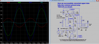
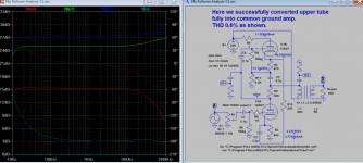
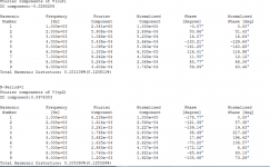
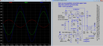
Here I have connected the bypass cap to top cathode via a resistor. This increases much (adjusted) gain for your need. This also fully converted the upper tube into a common ground amp, making it a dual common ground amps, let me know your comment.
If stability is a concern we still can loop some global nFB from top plate to bottom cathode. Mona, I am adopting your sch, please take a look.
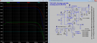
Edit: THD 0.192149%(0.202580%
"a pretty mediocre top active device"
Here I have connected the bypass cap to top cathode via a resistor. This increases much (adjusted) gain for your need. This also fully converted the upper tube into a common ground amp, making it a dual common ground amps, let me know your comment.
If stability is a concern we still can loop some global nFB from top plate to bottom cathode. Mona, I am adopting your sch, please take a look.
Edit: THD 0.192149%(0.202580%
Attachments
Last edited:
Output impedance is irrelevant for calculating the boostrap resistance, as you should always calculate voltage gain assuming no external load. For a mu-follower (or any other CCS-like configuration) the impedance presented by the upper valve is ra+(mu+1)Rk. Use this to calculate the voltage gain into an open circuit.Koonw said:I just wonder how is the dynamic or bootstrap resistance is calculated if output impedance is significantly higher than CF.
Then, find the stage transconductance into a short circuit - bootstrapping is disabled by the short. Divide one into the other to find the output impedance.
It is a CCS for voltage gain into an open circuit, but not for transconductance into a short circuit - hence lower cathode bypass affects output impedance. Note that as soon as you apply an external load the bootstrapping becomes less effective; your factor of 0.9 is just a wild guess on this, so better to actually calculate than guess.But if it is near CCS, bypass or not make no difference, but in practice some do notice a difference.
I'm not sure I understand the question. The only place for mu-follower output is the upper cathode. If not, it is not a mu-follower.And where in your opinion is best place for output?
A Triode makes a pretty mediocre top active device. A Pentode is much better--but complicated, and a MOSFET is even better than a Pentode. Its easier/simpler and there's no heater/cathode voltage problem to worry about too.
MOSFET on top--Whats Not to like! Its my preferred gain-stage, and adaptable to all sorts of tubes from high Mu low current tubes to low Mu high current types.
In what sense is a top triode 'mediocre' and a pentode or MOSFET 'better'?
Cheers
Ian
I'm not sure I understand the question. The only place for mu-follower output is the upper cathode. If not, it is not a mu-follower.
Yes of course the top tube contribute most of the output, if not all. Should it be right on top of cathode or at the bottom of cathode resistor? If on very top, that would includes the self-bias circuit of top tube, what is your insight to connect on top, distortion and sonic wise. So this is FAQ question, but in particular the Mu follower Rout is already higher if connect wouldn't it load down further (so is the rest of bootstrap path as you pointed out)? TIA
In your last schematic you introduce positive feedback via R10+C2.More gain, more distortion !
Mona
Mona
In what sense is a top triode 'mediocre' and a pentode or MOSFET 'better'?
Cheers
Ian
This article explains it much better than I ever could, but to boil it down to one word,--Gain.
http://www.fetaudio.com/wp-content/uploads/2003/09/Mu-Stage.pdf
In your last schematic you introduce positive feedback via R10+C2.More gain, more distortion !
Mona
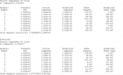
Yes, that 0.6%, but I readjusted value got it down to <0.2%. After all the beauty of this circuit more PF less distortion, believe it or not. I tried nFB, the distortion is higher, so go figure 🙂
Attachments
It is a CCS for voltage gain into an open circuit, but not for transconductance into a short circuit - hence lower cathode bypass affects output impedance. Note that as soon as you apply an external load the bootstrapping becomes less effective; your factor of 0.9 is just a wild guess on this, so better to actually calculate than guess.
I check with sim for open circuit gain of the top tube is 8.41 in 7.21 out, so 7.21/8.41=0.857, yes lower than 0.9. So 7700/(1-0.857)=54K, compared to 77K if 0.9. If connect via cap to bottom tube, it is 0.846 which gives 50K. So have to increase bootstrap resistor from 8.2K to 33K makes it effect resistance over 200K.
Reference to sch of last post, with this bootstrap I only get CCS for a particular output level, varied the load the current stays the same, but if a different output the current is another value, the current goes up as load goes down, appears to give better regulation.
Last edited:
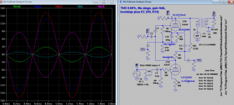
So--22V ish peak, and 0.6% dist. Not hugely better than that could be obtained by a plate resistor.
I wonder what the performance would be with 50V peak...?
--Is it able to swing that far?
MOSFET on top will allow much greater swing, and comparable if not lower distortion up to around 80V peak or more easily.
I wonder what the performance would be with 50V peak...?
--Is it able to swing that far?
MOSFET on top will allow much greater swing, and comparable if not lower distortion up to around 80V peak or more easily.
And with C5 at the other end of R3 ?
Did you measure the distortion at the same output level ?
Mona
Did you measure the distortion at the same output level ?
Mona
And with C5 at the other end of R3 ?
Did you measure the distortion at the same output level ?
Mona
Yes, that is TP2 right? Distortion for both are < 0.2% (note that TP2 level is much higher.) If same level it is 0.104722%(0.121679%).
Attachments
Last edited:
So--22V ish peak, and 0.6% dist. Not hugely better than that could be obtained by a plate resistor.
I wonder what the performance would be with 50V peak...?
--Is it able to swing that far?
MOSFET on top will allow much greater swing, and comparable if not lower distortion up to around 80V peak or more easily.
2 tubes better than one, apply more voltage up to 500V, more swing. Here is 60V snapshot at 450V, but distortion has not been fine tuned.
Attachments
Last edited:
As I said, at the cathode. Output from the bottom of the top cathode bias resistor will make little difference apart from a rise in output impedance, so why do it?Koonw said:Should it be right on top of cathode or at the bottom of cathode resistor?
I don't understand.So this is FAQ question, but in particular the Mu follower Rout is already higher if connect wouldn't it load down further (so is the rest of bootstrap path as you pointed out)?
As I said, at the cathode. Output from the bottom of the top cathode bias resistor will make little difference apart from a rise in output impedance, so why do it?
I don't understand.
Ok never mind, you already make your point good. In my application, I use the cathode out for feedback, so I connect to bottom of resistor, and does make little difference (measurable distortion etc..), TK.
We know Mu follower or stage use bootstrap not only present a large load but also some errors correction at bootstrap resistor R9. Would appreciate anyone try to explain how R10 can cut distortion to real low, look like some null error correction taken place, thanks. And that is so would a perfect zero feedback headphones amp?
Attachments

Last edited:
Koonw:
It would appear that you are going towards something more like a totem pole balanced P device and N device with self split kind of arrangement instead of a mu follower.
I would advise you to drive your headphones with a long tailed pair.
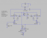
When building open loop circuits, first step is to choose a tube with good curves. That leaves 12AU7 out of consideration; instead, choose for example 6SN7 which is cheap and easily available, and has good curves.
Attached is my 6SN7 LTP schematic. It can be driven with a single input (other input is then grounded). This will increase distortion a little bit. Best results are with a balanced input (driving both inputs).
Sims are of course sims and numbers are presented only as a curiosity, but this circuit does in fact produce incredibly clean output for small power needs such as headphones. I've done this with a number of tubes including 2C22 and 6SN7 with excellent results.
With 52 VPP signal between plates;
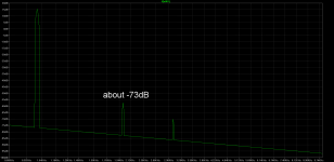
Single input: Total Harmonic Distortion: 0.023%
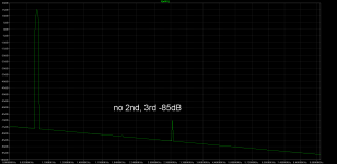
Balanced input: Total Harmonic Distortion: 0.005%
Attached also FFTs with single and balanced input signals.
It would appear that you are going towards something more like a totem pole balanced P device and N device with self split kind of arrangement instead of a mu follower.
I would advise you to drive your headphones with a long tailed pair.
When building open loop circuits, first step is to choose a tube with good curves. That leaves 12AU7 out of consideration; instead, choose for example 6SN7 which is cheap and easily available, and has good curves.
Attached is my 6SN7 LTP schematic. It can be driven with a single input (other input is then grounded). This will increase distortion a little bit. Best results are with a balanced input (driving both inputs).
Sims are of course sims and numbers are presented only as a curiosity, but this circuit does in fact produce incredibly clean output for small power needs such as headphones. I've done this with a number of tubes including 2C22 and 6SN7 with excellent results.
With 52 VPP signal between plates;
Single input: Total Harmonic Distortion: 0.023%
Balanced input: Total Harmonic Distortion: 0.005%
Attached also FFTs with single and balanced input signals.
Attachments
Koonw:
It would appear that you are going towards something more like a totem pole balanced P device and N device with self split kind of arrangement instead of a mu follower.
Thank, if you know more let me know, N, P device? You mean you know similar solid state circuit?
I would advise you to drive your headphones with a long tailed pair.
When building open loop circuits, first step is to choose a tube with good curves. That leaves 12AU7 out of consideration; instead, choose for example 6SN7 which is cheap and easily available, and has good curves.
Yes 12au7 has higher distortion, and I heard folk say can do 0.2% at 10mA CCS. Why it should be different in your circuit or have you built and have already compared the sonic difference, so the conclusion is the more linear the tube, the better sound it is to you but not to everyone. Sorry no negative comment is intended, I just a bit disagree with basis of your advice.
Attached is my 6SN7 LTP schematic. It can be driven with a single input (other input is then grounded). This will increase distortion a little bit. Best results are with a balanced input (driving both inputs).
Sims are of course sims and numbers are presented only as a curiosity, but this circuit does in fact produce incredibly clean output for small power needs such as headphones. I've done this with a number of tubes including 2C22 and 6SN7 with excellent results.
With 52 VPP signal between plates;
Single input: Total Harmonic Distortion: 0.023%
Balanced input: Total Harmonic Distortion: 0.005%
Attached also FFTs with single and balanced input signals.
Please give the figure for 12au7 or ecc82 for my comparison, thank you very much. I might be able to tweak to get even lower. I agree that with 6sn7 in my sim is also a bit lower, but in this level of distortion the 2nd and 3rd harmonic is the same as well same as your attached figure. I am not a big fan of solid state yet but who knows 🙂 I just stick to 12au7 in sim and occasionally plug in other tube for comparison. R10 is 16.31K for 6sn7 not far 13.8K for 12au7 for lowest distortion, at least the circuit is doing something the same way for different tubes. But you say your circuit have relied solely on tubes type for errors and no other means except CCS and PP?
Last edited:
Yes 12au7 has higher distortion, and I heard folk say can do 0.2% at 10mA CCS. Why it should be different in your circuit or have you built and have already compared the sonic difference, so the conclusion is the more linear the tube, the better sound it is to you but not to everyone. Sorry no negative comment is intended, I just a bit disagree with basis of your advice.
Please elaborate what you disagree on.
Since you sim and post distortion figures, you clearly care about distortion (as you should if you're an high fidelity enthusiast).
One way to reduce distortion is to use feedback loops. Then it becomes less important what you put inside the loop, as a gross simplification you just need gain inside the loop.
Or, when using only a little bit NFB, you can use a not so good triode for example, and the NFB 'fixes' the distortion of the not so good device.
When you don't use NFB, i.e. you design an open loop circuit, you don't have anything (at least very effective) to reduce the distortion, so you simply need to have a gain device that doesn't produce much distortion in the first place.
Therefore, I find that when building open loop, the most important first design choise is to pick tubes that have good curves, and then utilize that device in a way to make best use of those curves (i.e. don't allow any distortion to be produced).
This is paramount because there is nothing 'afterwards' to remove the distortion.
So if you are interested in distortion figures, and you plan to build an open loop (no NFB) circuit, you need to use tubes that have the best curves.
Look at the curves of the 12AU7. It is not meant for any serious audio reproduction. Look at the curves of the 6SN7. When building open loop (no distortion 'clean up') why would you choose the 12AU7 when there are other options just as cheap and easy to buy?
As for my proposed LTP circuit, I have built it using many tubes, and it does produce better results with tubes that have good curves, and worse results with tubes that have not so good curves.
For example using 6V6 triode strapped didn't produce as good results as 4P1L triode strapped (which produces the very best results I've ever had). Look at the respective curves of these tubes triode strapped; you can instantly see why that is.
If you are not looking to linearise your circuit, why are you concerned with THD figures?
Please give the figure for 12au7 or ecc82 for my comparison, thank you very much. I might be able to tweak to get even lower.
Sure, here's some 12AU7 THD numbers with about 52 VPP between plates:
Single input used: Total Harmonic Distortion: 0.076%
Balanced input used: Total Harmonic Distortion: 0.015%
I just stick to 12au7 in sim and occasionally plug in other tube for comparison.
May I ask why you stick to this non-audio tube?
But you say your circuit have relied solely on tubes type for errors and no other means except CCS and PP?
I did not understand this, please elaborate.
Circuit I posted does get it's entire harmonic imprint from the tubes, within it's reasonable range (using more than say 25mA per tube or very low plate resistance tubes under 900 ohms will require well chosen FETs on top).
"Please elaborate what you disagree on."
It's the EC and not GNFB, I think you got mixed up. Please analyse again if that is so that also my question to everybody. The distortion figure is lower than most folk can do with CCS on this tube which is 0.2%, how can this sch can do lower? Not by GNFB I think. Where is your distortion figure for 12au7 of your own sim then?
It's the EC and not GNFB, I think you got mixed up. Please analyse again if that is so that also my question to everybody. The distortion figure is lower than most folk can do with CCS on this tube which is 0.2%, how can this sch can do lower? Not by GNFB I think. Where is your distortion figure for 12au7 of your own sim then?
Last edited:
- Status
- Not open for further replies.
- Home
- Amplifiers
- Tubes / Valves
- Mu Follower Analysis