This is the 811A SE amplifier I built some 4 years ago. Max. power output is some 15 W and the linearity is quite good even without any GNFB.
This looks simpler then other schematics I've looked at,,, The 680K pot is the volume control, correct? Any suggested substitutions for 6N1P, I like to use what I have, if possible...
I'm pretty new at this, and appreciate teh input and schematics...
Regards,
John
...The 680K pot is the volume control, correct? Any suggested substitutions for 6N1P...
680k pot is for adjusting the pentode stage to optimum distortion.
It is not very critical at all, but the schematic is from my prototype and I usually have some adjustments that are not actually needed, but usefull when prototyping.
I also used one half of 6N6P as a driver.
I assume 6DJ8 could be one that works, 6BL7 for sure...
Very few manufacturers, DIYer's ever give the out put impedance.
Phil
I usually do such measuremets to my prototypes and not that much listening tests. I never built this amplifier as a complete stereo version, only one channel prototype.
Would like to see a few pics of your amp if they are easily linked
Regards, KM
")
I found one:
Edit: A couple more with better resolution:
My output tube was soviet G811.
Attachments
Last edited:
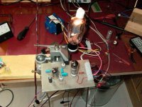
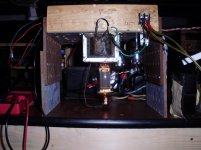
I built one channel of the amp in post 12,,, Its rough, but works pretty well... Voltages are close to specs, and its running on 2 different FTs (AC, for now) so the B+ can be adjusted with a variac, without affecting teh heater V...
Looks promising, so far... DC heater supply is the way to go, tho...
Still trying to learn!!!
Regards,
John
Looks promising, so far... DC heater supply is the way to go, tho...
Still trying to learn!!!
Regards,
John
Attachments
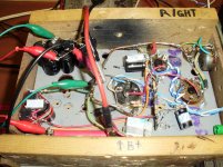
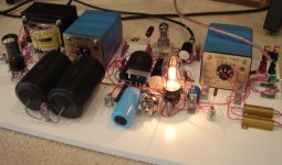
I always prefer a classic breadboard approach for new designs. It's much easier to make changes, much safer from inadvertent shorts with probes and loose components and you can easily move it around. Attached is a pic of the initial 3C24 SE amp. Granted, it takes a bit of extra time to do the initial breadboard, but you reuse much of it for later designs, as the BB was initially done for a SE with single-plate 2A3s.
Regards, KM
Regards, KM
Attachments
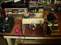
Nice layout,,, I've used these "test mules" for 4-5 amp builds so far...I find it easier to be able to flip teh chassis over for access to the tube pins, and use a color code to follow wires...
If I am sure of teh circuit, I make a masonite "chassis" the same size as teh final chassis and try everything in its ultimate position, to make sure there's no hum before final assembly...
Whatever works, have fun...
Regards,
John
If I am sure of teh circuit, I make a masonite "chassis" the same size as teh final chassis and try everything in its ultimate position, to make sure there's no hum before final assembly...
Whatever works, have fun...
Regards,
John
Last edited:
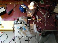
Here's some voltage readings I got, with the amp warmed up no signal, at 254VDC B+,,,, I added a 1.0/200V input cap, to protect CDP...
Other then the hum, it sounds pretty good...
811,,,340V Plate, 22V Grid
6V6,,, 268V Plate
6SN7,,, 69V Plate
Regards,
John
Other then the hum, it sounds pretty good...
811,,,340V Plate, 22V Grid
6V6,,, 268V Plate
6SN7,,, 69V Plate
Regards,
John
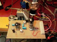
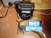
They are 50ohm 5W resistors,,,
I just built a DC power supply for teh 811 filaments,,, Readings across resistors are... Pin 1 to ground 4.46VDC,, and pin 4 to ground -1.58VDC... 6.04Vseems low for heater V but, I can use a bigger transformer... The grid is 23.7 VDC...
However, with just teh 811 filament on DC teh hum is almost gone, I'll build another DC supply for the driver tubes, should quiet it down...
Thanks for teh help!!!!
Regards,
John
Attachments
Last edited:
You can calculate the grid current by measuring the voltage across the 8.2K resistor which feeds the plate of the 6V6. Would suggest measuring the resistance with the circuit off, caps drained to zero volts and the 6V6 removed, this way the calculation is more accurate.
Plate current.... measure the voltage across the pair of 50 ohm resistors, calculate each current and add together (you now have plate + grid current) then subtract the grid current calculated above and you have plate current.
Regards, KM
Plate current.... measure the voltage across the pair of 50 ohm resistors, calculate each current and add together (you now have plate + grid current) then subtract the grid current calculated above and you have plate current.
Regards, KM
You can calculate the grid current by measuring the voltage across the 8.2K resistor which feeds the plate of the 6V6. Would suggest measuring the resistance with the circuit off, caps drained to zero volts and the 6V6 removed, this way the calculation is more accurate.
Plate current.... measure the voltage across the pair of 50 ohm resistors, calculate each current and add together (you now have plate + grid current) then subtract the grid current calculated above and you have plate current.
Regards, KM
OK,, thanks, I'll give it a try... Its the math part that kills me, tho!
Regards,
John
You can calculate the grid current by measuring the voltage across the 8.2K resistor which feeds the plate of the 6V6. Would suggest measuring the resistance with the circuit off, caps drained to zero volts and the 6V6 removed, this way the calculation is more accurate.
Plate current.... measure the voltage across the pair of 50 ohm resistors, calculate each current and add together (you now have plate + grid current) then subtract the grid current calculated above and you have plate current.
Regards, KM
OK,, Here goes,,,Grid,... 8.2K reads 8.2K( 8200) V across, & 79.2V...
So, 79.2 /8200=.0097
Plate resistors read 4.53 and -1.47= 6V and 50.4 + 50.4 ohms= 100.8,
6/100.8=.0595,,,,,, .0595-.0097=.0499
Don't know if the math is right, but the measurements are as close as the meter is....
Regards,
John
Update ...
Built a DC filament supply for the 811 with a variable transformer, still using the 50ohm resistors,,, Got the V back up to 6.3vdc, moved the other DC heater supply to the other tubes, and get no hum at all...
Experimenting with feed back, and it seems the amp would need more gain to use it... Is there an easy way to put the unused section of the 6SN7 in series with the 1st section, to boost gain some? I see the 6SL7 used that way on a 6BG6 SE amp I've been working on, but not sure how to size resistors/caps properly...
Thanks ..
Regards,
John
Nobu K Shishido; used 430 volts @100Ma, 3.5k out put transformer for 14 Watts . Nobu Used an inter- stage.
I used a 6BX7 cathode follower.
For the PP 811A amp I used 2.2K P--P and 600volt,70Ma current both tubes; Tried 15K P-P Did not like the sound!!. 5K works very well with cathode coupling. The important thing is to keep the voltage low and current High. Easy to get, 100 to 150 watts. Much easier than using KT88's for 100 watts and the short life of the KT88, Russian 811A last for ever, and better sound.
Phil
Nobu K Shishido; used 430 volts @100Ma, 3.5k out put transformer for 14 Watts . Nobu Used an inter- stage.
I used a 6BX7 cathode follower.
For the PP 811A amp I used 2.2K P--P and 600volt,70Ma current both tubes; Tried 15K P-P Did not like the sound!!. 5K works very well with cathode coupling. The important thing is to keep the voltage low and current High. Easy to get, 100 to 150 watts. Much easier than using KT88's for 100 watts and the short life of the KT88, Russian 811A last for ever, and better sound.
Phil
This amp sounds a lot like the SE 6BG6 amp I've been working on,,, Can you post your schematic? Or is your amp PP...
Regards,
John
- Status
- This old topic is closed. If you want to reopen this topic, contact a moderator using the "Report Post" button.
- Home
- Amplifiers
- Tubes / Valves
- SE 811 amp schematic...