There have been a couple of threads that have some discussion about this kit, but I thought I'd pull a few thoughts together here. It may be simpler for future readers to have the links and a few pictures in one thread.
To start: The 'kit' is sold via eBay and is titled 'SE EL34B Amp DIY Kit' - a search will turn it up
It's been discussed here and also over there
The 'kit' comes with a schematic and non-matching layout diagrams. In this thread there was a strong recommendation (from Eli Duttman and Ezequiel) for a different SRPP circuit, using 6SN7 tubes (the kit has octal sockets/cutouts).
Link to the recommended circuit:
1.000.000 de Circuitos Eletrônicos Audio: SRPP 12AU7 / EL34 SE
That's what I built.
Attachments
It all worked out fine in the end, but I wouldn't recommend this kit, at all.
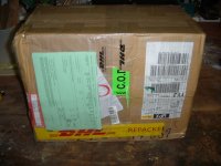
Shipping was expensive but fast, and the packing was fairly good (the usual Chinese crumbling styrofoam beadboard...).
Shipping was expensive but fast, and the packing was fairly good (the usual Chinese crumbling styrofoam beadboard...).
Attachments
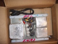
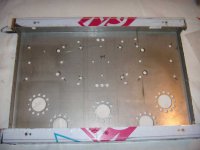
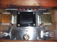
A few problems were obvious right away.....
No hole for the PT, and holes for the OT leads were too small to fit grommets (no grommets in kit...)
Stainless chassis - I hate working with stainless....but it is nice and shiny..
No hole for the PT, and holes for the OT leads were too small to fit grommets (no grommets in kit...)
Stainless chassis - I hate working with stainless....but it is nice and shiny..
Attachments
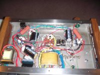
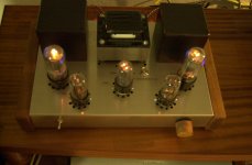
The kit recommendation was for a buss-style build.
These can be very nice-looking (and sounding, if you do them properly) but I haven't had much luck on the couple of occasions I've done a build with a buss.
I just slapped in some lug strips and got to work. Some of the extra lugs came in handy later, when I was 'adjusting' the PS to give the correct (lower) B+. (added another RC section).
I added switches for the NFB and also a 'Pentode/Triode' switch.
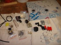
BTW- I didn't use any of the caps or resistors that came with the kit. The quality looked a bit suspect and the electrolytics were all radial-style, which I don't use with point-to-point wiring.
Not a very neat wiring job, but it works. Fortunately, it doesn't have to look pretty to sound pretty!
These can be very nice-looking (and sounding, if you do them properly) but I haven't had much luck on the couple of occasions I've done a build with a buss.
I just slapped in some lug strips and got to work. Some of the extra lugs came in handy later, when I was 'adjusting' the PS to give the correct (lower) B+. (added another RC section).
I added switches for the NFB and also a 'Pentode/Triode' switch.
BTW- I didn't use any of the caps or resistors that came with the kit. The quality looked a bit suspect and the electrolytics were all radial-style, which I don't use with point-to-point wiring.
Not a very neat wiring job, but it works. Fortunately, it doesn't have to look pretty to sound pretty!
Attachments

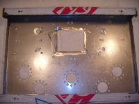
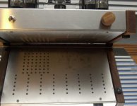
Something else which wasn't included in the 'kit' was a bottom cover. I really think all projects should have these, for safety's sake.
A piece of aluminum plate from the local recycling yard and some cutting and drilling later....
BTW, save those perforated steel bottom covers from old gear - they make good drilling templates. Just clamp to your new work and head for the drill press.....
A piece of aluminum plate from the local recycling yard and some cutting and drilling later....
BTW, save those perforated steel bottom covers from old gear - they make good drilling templates. Just clamp to your new work and head for the drill press.....
Attachments
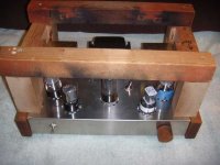
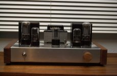
I also cut a couple of hardwood end plates to use instead of the supplied particleboard items, and made a matching knob.
I'm happy with the results- it sounds very good, and is dead-quiet when the music stops.
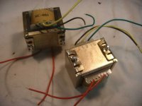
I ended up using EL34s (Russian equivalents), some NOS 6SN7s I had on hand, and a 5R4GYB rectifier.
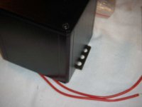
The power transformer is right at its limit - hot enough that I don't want to keep my hand on it for more than a few seconds - so I put the supplied PT cover on the shelf for another project.
I'm happy with the results- it sounds very good, and is dead-quiet when the music stops.
I ended up using EL34s (Russian equivalents), some NOS 6SN7s I had on hand, and a 5R4GYB rectifier.
The power transformer is right at its limit - hot enough that I don't want to keep my hand on it for more than a few seconds - so I put the supplied PT cover on the shelf for another project.
Attachments
Nice work. I'm sure your efforts will help those unfortunate souls who bought one of these and don't know what to do with their unfinished amp.
jeff
jeff
Thanks.
Memories of building real kits (Heathkits) back in the 70s flashed through my head when I was working on this thing.
Night and day difference...
Memories of building real kits (Heathkits) back in the 70s flashed through my head when I was working on this thing.
Night and day difference...
Without Eli and Ezequiel to point me in the right direction, the result would have been quite different.Nice work. I'm sure your efforts will help those unfortunate souls who bought one of these and don't know what to do with their unfinished amp.
jeff
A 'tip of the hat' to the folks who made suggestions in those previous threads.
This is a really helpful post, thanks.
In spite of your advice, I've just ordered one of these. I got my heart set on building a single-ended amp and the circuit you ended up building to looks good for me: EL34s are much cheaper than 2A3s or 300Bs but still probably powerful enough for my needs when in triode mode. When I costed up what I would need to build the circuit (including a chassis), it ended up quite a bit in favour of buying and modifying this kit (the decider was your positive comment in the other thread about the quality of the transformers).
I wanted to ask you about the power supply - did you get a measurement of the voltages with the PSU as specified in the kit diagram? I want, if possible, to stick with the standard PSU to avoid buying another choke or rectifier tube, however our mains here is at least 240v so, coupled with the fact that the kit's for 220v, I was wondering whether this is definitely too much for the improved circuit that you went with?
I've struggled to find data for either the 6SN7 or the triodes in the kit, so I was wondering if the improved circuit might be adapted for the kit triodes and whether the standard PSU would be more appropriate this way? I do have some 6SN7GTs if not.
Thanks,
Chris.
el34 like to ran hot. and feedback is a cheap fix for not enough B+. The input circuit is wrong also on the post 1 schematic. Needs to be higher resistance.
I run this circuit at B+ 430V (attached schematics):
I run this circuit at B+ 430V (attached schematics):
Attachments

Last edited:
I wanted to ask you about the power supply - did you get a measurement of the voltages with the PSU as specified in the kit diagram? I want, if possible, to stick with the standard PSU to avoid buying another choke or rectifier tube, however our mains here is at least 240v so, coupled with the fact that the kit's for 220v, I was wondering whether this is definitely too much for the improved circuit that you went with?
I didn't keep much in the way of notes about this build, but I recall dropping about 50 volts from the B+ by adding another RC section. For me, dropping the B+ was easier than changing other components to get the plate dissipation 'right' with the higher B+. However, you could certainly do that. If you don't already have Duncans PS designer software (free), you should download it-it's useful to get B+ close to where you want it. Resistors and caps are cheap- no need for another choke, IMO.
Getting tube data hasn't been difficult for me- there seem to be a few good sites out there. What sort of info were you looking for- the 'basics' or more extensive application notes?I've struggled to find data for either the 6SN7 or the triodes in the kit, so I was wondering if the improved circuit might be adapted for the kit triodes and whether the standard PSU would be more appropriate this way? I do have some 6SN7GTs if not.
Matching the B+ and the cathode resistors for the power tubes is more critical than the preamp stage, I think . I just took the advice I was given and switched to the different circuit with the preamp 6SN7s. I have a few tubes here, (and an excellent local source) so that wasn't a problem.
If you have efficient speakers, running in triode mode should be OK. The triode/pentode switch is handy, though I don't use it a whole lot.
Cheers
John
el34 like to ran hot..................
I run this circuit at B+ 430V (attached schematics):
You don't have problems with exceeding the max plate dissipation, using 430v? What (brand of) tubes are you using?
Thanks, I'll get that software. It was only the basic info that I wanted for those tubes, as I'd just like to use everything that comes with the kit (except the passive components). I do have a valve data CD from the Vintage Wireless website, I just haven't had chance to search it thoroughly yet. With the help of that software you mention I may be able to adapt the circuit you used to the 6SL7s.
My speakers are only 89db IIRC, so I think the triode switch may be a necessity for me!
How would you rate the end result you got, is it true 'audiophile' quality?
Thanks,
Chris.
My speakers are only 89db IIRC, so I think the triode switch may be a necessity for me!
How would you rate the end result you got, is it true 'audiophile' quality?
Thanks,
Chris.
I received my kit the other day (pretty much as described above, although the main transformer hole is now cut out for you!) and I've been studying the schematic some more. I see that with the exception of triode mode and NFB, the circuit is the same as the recommended one that you (VictoriaGuy) went with. Obviously the voltages and some of the component values differ, plus the preamp valves have been changed to 6SN7s.
What is it in particular that is better about the recommended circuit over the one that comes with the kit? Is it mainly the NFB and triode connections, or is the lower voltage and different component values that are a major factor?
Thanks,
Chris.
What is it in particular that is better about the recommended circuit over the one that comes with the kit? Is it mainly the NFB and triode connections, or is the lower voltage and different component values that are a major factor?
Thanks,
Chris.
You don't have problems with exceeding the max plate dissipation, using 430v? What (brand of) tubes are you using?
Plate dissipation is one thing, max voltage is another. I totally agree with DavesNotHere, I m breadboarding a EL34 SET with a 410 V supply and it feels like they are almost voltage starved. Keep in mind that max plate voltage for those is 880 V. Of course you can't just up the voltage, you have to have a higher output transformer impedance too, and also a higher cathode resistor to bias it properly.
For example, I have 380 V cathode to plate (that is the way to measure it) and 4500 Ohm transformer, 470R cathode resistor. I would happily go to 460V, but this limits the smoothing capacitor choices.
- Status
- Not open for further replies.
- Home
- Amplifiers
- Tubes / Valves
- Building something better with a Chinese SE EL34B Amp DIY Kit