Hey all! A buddy of mine and I took to building a small stereo amp from a kit that we got on eBay. It was quite the process, but we finally finished it today. The kit did not come with any instructions and only came with a set of 3 schematics and a parts list.
When we finished the amp and powered it up, all of the tubes lit up and there were no sparks/flames or smoke. However, I could hear some cyclical noise coming from the chassis. When connecting it to a source and output, it sounds as if it is in a feedback loop along with a nasty hum. Only if I turn the pre way up can I hear any signal. The volume does not affect the output level of the noise and it comes out of each of the 4 channels. If connected to the right ground, the right channel is louder than the left and vice versa.
When we were finished, we were left with 2 resistors that had no home. One was a 2w 5k and the other was a 220k. The parts list show that they belong with the kit, but we could not find where on the schematics they belong. After checking on the power stage schematic, we did see that there was a 220k resistor present, but on the other 2 it was not there. Because we were not 100% we felt it was safest to add it.
However, after all is said and done, there is no place for this 5k resistor that we can see.
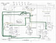
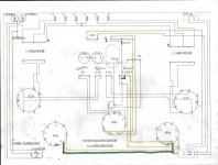
I have attached all 3 of the schematics and a photo of the underside of the amp. Also, there is a larger version of the build photo at the link. We have been tracking it on a blog if anyone is looking for more information.
Any help whatsoever would be amazing. We have not gone ahead and prodded any further and will sit tight until we know what to try.
Thanks again for reading all of this and I hope to hear from some of you!!
Lenny
The DIY Experiment (Attenuated Attempts)
http://3.bp.blogspot.com/_D8VB90EwTZ...00/amp+4.JPG
When we finished the amp and powered it up, all of the tubes lit up and there were no sparks/flames or smoke. However, I could hear some cyclical noise coming from the chassis. When connecting it to a source and output, it sounds as if it is in a feedback loop along with a nasty hum. Only if I turn the pre way up can I hear any signal. The volume does not affect the output level of the noise and it comes out of each of the 4 channels. If connected to the right ground, the right channel is louder than the left and vice versa.
When we were finished, we were left with 2 resistors that had no home. One was a 2w 5k and the other was a 220k. The parts list show that they belong with the kit, but we could not find where on the schematics they belong. After checking on the power stage schematic, we did see that there was a 220k resistor present, but on the other 2 it was not there. Because we were not 100% we felt it was safest to add it.
However, after all is said and done, there is no place for this 5k resistor that we can see.
I have attached all 3 of the schematics and a photo of the underside of the amp. Also, there is a larger version of the build photo at the link. We have been tracking it on a blog if anyone is looking for more information.
Any help whatsoever would be amazing. We have not gone ahead and prodded any further and will sit tight until we know what to try.
Thanks again for reading all of this and I hope to hear from some of you!!
Lenny
The DIY Experiment (Attenuated Attempts)
http://3.bp.blogspot.com/_D8VB90EwTZ...00/amp+4.JPG
Attachments
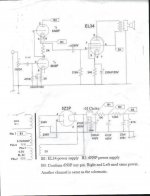
Looks like the 5k goes into the power supply, between the first two electrolytic caps.
CAREFULLY measure voltages at the power supply output and at each of the tube pins and make a voltage map on the schematic. That should clarify things and help us figure out where the problem is.
CAREFULLY measure voltages at the power supply output and at each of the tube pins and make a voltage map on the schematic. That should clarify things and help us figure out where the problem is.
Thanks SY! Regarding the 5k, we did put one between the 2 caps, but there was one left over when we were finished. Also, we have the 220k over the 47uf on the 5z3p as shown on the first schematic. Does that seem to make sense as it does not show up on the other 2 schematics, we were not sure if it belonged there.
Hi,
Your first post looks closest to correct. As SY says you need to check the voltages with a multi-meter on B1,B2,B3 and tell us what you get to Gnd. The 220K is probably a Discharge resistor to stop the B+ staying UP after power off. Don't switch it on with out the speaker connected or a load resistor!
Regards
M. Gregg
This amplifier is already being discussed on this thread <http://www.diyaudio.com/forums/tube...z3p-amplifier-kit-any-thoughts-schematic.html > Seems not to be too popular. ")
Tony
Tony
Hi,
Don't forget to check the B+ is dead before you touch anything with your hands!
Also where is B3 connected to? Looks like it should lift the heaters not connect to cathode.
What voltage have you got at pin 3 of the 6N9P? Also when you measure this you should hear through the speaker a "noise" as you connect the meter. Pin 3 to Gnd DC voltage!
Regards
M. Gregg
Last edited:
That 220k resistor does nearly nothing- the schematic shows a 47k bleeder, which would swamp the effect.
I thought there was a 120K and a 5K in series with the 47K to the 47uF after the rectifier so would we have a parallel value?
Regards
M. Gregg
Thanks for the input! We are reading all of this and trying to keep up. We are in over our heads, but are trying hard to get up to speed. So, I will power it up, with a load on it and measure the voltage at the 6n9p and at pin8 of the 34s. Is there anything else that would be helpful? Would any other photos help and any other precautions in getting these measurements?
Please take care,
Make sure you don't touch anything without checking that the B+ is dead.
Others will help when we have values. I dont think photos will help at this point.
Voltage readings are of more use!
So give us a list or write them on a copy of the circuit showing left and right channels.
Make sure you don't touch anything without checking that the B+ is dead.
Others will help when we have values. I dont think photos will help at this point.
Voltage readings are of more use!
So give us a list or write them on a copy of the circuit showing left and right channels.
Last edited:
I thought there was a 120K and a 5K in series with the 47K to the 47uF after the rectifier so would we have a parallel value?
That's true, but that combination already will bleed the caps- the 220k doesn't really add value.
can you also show the complete parts listHey all! A buddy of mine and I took to building a small stereo amp from a kit that we got on eBay. It was quite the process, but we finally finished it today. The kit did not come with any instructions and only came with a set of 3 schematics and a parts list.
When we finished the amp and powered it up, all of the tubes lit up and there were no sparks/flames or smoke. However, I could hear some cyclical noise coming from the chassis. When connecting it to a source and output, it sounds as if it is in a feedback loop along with a nasty hum. Only if I turn the pre way up can I hear any signal. The volume does not affect the output level of the noise and it comes out of each of the 4 channels. If connected to the right ground, the right channel is louder than the left and vice versa.
When we were finished, we were left with 2 resistors that had no home. One was a 2w 5k and the other was a 220k. The parts list show that they belong with the kit, but we could not find where on the schematics they belong. After checking on the power stage schematic, we did see that there was a 220k resistor present, but on the other 2 it was not there. Because we were not 100% we felt it was safest to add it.
However, after all is said and done, there is no place for this 5k resistor that we can see.
I have attached all 3 of the schematics and a photo of the underside of the amp. Also, there is a larger version of the build photo at the link. We have been tracking it on a blog if anyone is looking for more information.
Any help whatsoever would be amazing. We have not gone ahead and prodded any further and will sit tight until we know what to try.
Thanks again for reading all of this and I hope to hear from some of you!!
Lenny
The DIY Experiment (Attenuated Attempts)
http://3.bp.blogspot.com/_D8VB90EwTZ...00/amp+4.JPG
can you show the complete parts list also
There isn't a parts list included with the kit (I know, I bought one). Basically you get everything indicated in the schematic plus a bunch of hardware.
Check out the ebay ad.
BTW, I would NOT recommend this kit.
If you have a specific question, just ask- I'm glad to help.
John
then how do you know they didnt put an extra one in by mistake..my kit was missing some bolts..ya i got the same kit also. i did get the transformer to sit in with the wires underneith. had to cut the hole bigger .havent gotter finished yet..long way ta go yet..just wondering if you wired it for 110v or220v
then how do you know they didnt put an extra one in by mistake..my kit was missing some bolts..ya i got the same kit also. i did get the transformer to sit in with the wires underneith. had to cut the hole bigger .havent gotter finished yet..long way ta go yet..just wondering if you wired it for 110v or220v
Since I'm in Canada, I wired it for 110v. I put the two primary windings in parallel, but apparently the seller told another hapless buyer to 'just use one' of the primary windings.
Are you building from the schematic or the layout diagrams?
If you haven't got it finished, you might consider using a different circuit with the same general parts (tubes, iron).
I don't know if you have found some of the other threads on this kit:
Trouble with a DIY EL34 Tube Amp Kit - AudioKarma.org Home Audio Stereo Discussion Forums
http://www.diyaudio.com/forums/tubes-valves/175300-el34b-6n9p-5z3p-amplifier-kit-any-thoughts-schematic.html
John
ya im also in canada. but thinking on 220v..wish everything here was 220v..i think all new houses should have 11ov and 220v in everyroom.anyways the seller told me for 110v to use one black wire and one red instead of 2 red and 2 black.. so for im useing the wiring diaghram that came with the amp.
so far im useing the wiring diagram that came with the amp.
Well, be careful. My 'kit' (so-called) came with three sheets of paper-no parts list. (But on rereading, I notice that the OP mentions a parts list.)
2 layout diagrams with Chinese notation, and 1 schematic.
The layout diagrams and the schematic don't match exactly, so be careful which one you use.
e.g. Schematic shows a voltage divider in the PS to apply +60vDC to one side of the AC preamp heaters, layout diagram shows the CT of the preamp heater winding grounded. Not a good idea to do both....
There are some pointed comments about the circuit in the posted threads; I'm building mine into the Ezequiel-recommended circuit, which Eli Duttman also suggested.
John
Last edited:
- Status
- This old topic is closed. If you want to reopen this topic, contact a moderator using the "Report Post" button.
- Home
- Amplifiers
- Tubes / Valves
- Trouble with a DIY EL34 Tube Amp Kit