Ezequiel-recommended circuit...what is that
Did you read the other threads on this kit that we are talking about? (see above for some 'starter links')
Attachments
i noticed that on the 3.5k transformers there are 2 red wires..1 is com and 1 is 3.5k..if you look at the diagraham the com on 1 transformer gos to pin#3 on that tube yet on the other transformer they are reversed..it goes to pin#4 .or am i seeing things wrong here..did you notice this
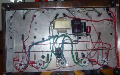
maybe im seeing things but the black wire going to the power cord ground prong from the transformer is a live wire like the red wire..and the ground wire for the power cord should be the yellow and green wire from the transformerThere isn't a parts list included with the kit (I know, I bought one). Basically you get everything indicated in the schematic plus a bunch of hardware.
Check out the ebay ad.
BTW, I would NOT recommend this kit.
If you have a specific question, just ask- I'm glad to help.
John
maybe im seeing things but the black wire going to the power cord ground prong from the transformer is a live wire like the red wire..and the ground wire for the power cord should be the yellow and green wire from the transformer
I'm not sure I understand all of what you are saying.
re: The yellow/grn wire from the transformer - this is a 'shield' wire of some kind which should be/can be attached to chassis ground. You must have a separate green wire from the IEC AC inlet ground lug to the chassis, for safety, as far as I know.
re: Black wire - are you talking about the primary side black (low side of primary winding) or the center-tap on the preamp heater secondary winding (the '0' in the 3.15-0-3.15 winding)
John
I don't see that on the diagrams I got....can you post a scan (jpg) of the diagram you are following, which shows that?i noticed that on the 3.5k transformers there are 2 red wires..1 is com and 1 is 3.5k..if you look at the diagraham the com on 1 transformer gos to pin#3 on that tube yet on the other transformer they are reversed..it goes to pin#4 .or am i seeing things wrong here..did you notice this
I like to follow schematics, so I don't pay much attention to layout diagrams like the ones that came in the 'kit'.
John
Aren't the 12AU7 heaters wired incorrectly in the last schematic posted? Should be 6v to the heater's center-tap, no?
http://www.diyaudio.com/forums/tubes-valves/181579-trouble-diy-el34-tube-amp-kit.html#post2460052
EDIT: Oh, I get it. Treating each triode as a separate tube. My bad, but that's, IMO, a dangerous way to diagram it.
..Todd
http://www.diyaudio.com/forums/tubes-valves/181579-trouble-diy-el34-tube-amp-kit.html#post2460052
EDIT: Oh, I get it. Treating each triode as a separate tube. My bad, but that's, IMO, a dangerous way to diagram it.
..Todd
Last edited:
Aren't the 12AU7 heaters wired incorrectly in the last schematic posted? Should be 6v to the heater's center-tap, no?
http://www.diyaudio.com/forums/tubes-valves/181579-trouble-diy-el34-tube-amp-kit.html#post2460052
EDIT: Oh, I get it. Treating each triode as a separate tube. My bad, but that's, IMO, a dangerous way to diagram it.
..Todd
I'm using 6SN7s, not 12AU7, so I didn't pay much attention to the heater wiring on that schematic.
A bit unusual, I guess.
Dangerous? I don't think so.
Well, the builder would have to look up the pinout for the 12AU7 in any case, and if a person can't figure out the 4,5 -9 system from the pinout, it's probably a signal that they're not ready for a scratch build.
BTW, 'dangerous' is what is shown in the layout diagrams for this Chinese kit - power inlet with no ground connection shown.
(See post above..)
John
hi lenny..i think you got the black and red wires going to the power cord wrong..the black one is connected to the ground prong.there should be a green wire from that prong to the chassis for ground.plus the black wire should go to the prong that you have no wire on..im just going by the pictures ..maybe you have noticed and corrected this already
did you notice the 0.33uf caps are showing 0.22uf caps on the layout..could this be causeing the bass problem
- Status
- Not open for further replies.
- Home
- Amplifiers
- Tubes / Valves
- Trouble with a DIY EL34 Tube Amp Kit