Thanks guys, much clearer!
I'll take some time to digest this and look at the maths, but I now see that much of this is related to cold start on the input tubes. Very helpful explanations for those unfamiliar with these kind of regs.
Andy I feel your pain. I just went through this. Although it’s been said not to, I put a 10 ohm resistor in line with my 2 0D3’s and measured the current while operating. I adjusted the resistor to give me a little over 5MA under load. Has seemed to work good. Not recommending this it’s just what worked for me. I’m maths challenged at times.
"as long as you promise never to run it with the amplifier tubes unplugged for more than a couple of seconds".
Remember, if you design an amplifier . . .
Consider special situations like the above
Think about who will use it in the future:
Your heirs.
Another person you sell it to, or give it to, a tube roller who insists on changing tubes live (very bad in several ways, but some do that and risk the amplifier and the speakers too).
A service person who tries to fix it for your heirs.
Yourself when your memory is not so perfect.
Etc.
Design an amplifier to be robust for all kinds of situations, including first turn-on tests,
Power Mains Hot Starts (amp is warm, and the power goes off for a couple of seconds, and comes back on again), etc.
Examples:
A single ended mono-block amplifier with a choke loaded B+ of 315V, and using 400V filter capacitors (when the output tube fails to draw current, the B+ increases to 495V . . .
Ouch! Those poor 400V B+ capacitors.
Or slow warming output tubes, and solid state B+ rectifier, same rising B+ voltage until the output tube warms up.
Robust versus Busted.
Last edited:
I adjusted the resistor to give me a little over 5MA under load.
Holy moly that's a lot of amps!!!
Holy moly that's a lot of amps!!!
If you got 242V, then you can time travel.
Remember, if you design an amplifier . . .
Consider special situations like the above
I don't disagree with what you wrote and it is certainly worth reminding people of. In this case though you are not likely to cause a catastrophic failure in the event you pull the amplifier tubes and turn it on. Assuming you have set the gas regulator to the mid point of the operating range it will only take 57.5 mA with the amplifier tubes removed. The anode voltage at the gas tube will rise and if you leave it there too long it will never return to the design voltage. The fix is a new gas tube. If you are concerned about future users, make sure you are not going to smoke things by running the circuit at the unregulated supply voltage for an extended period.
( over 5MA) Holy moly that's a lot of amps!!!
Play this a thousand times.
Popping a 5000A Fuse - YouTube -- intro, prep
Popping a 5000A Fuse - YouTube -- fun starts
I don't disagree with what you wrote and it is certainly worth reminding people of. In this case though you are not likely to cause a catastrophic failure in the event you pull the amplifier tubes and turn it on. Assuming you have set the gas regulator to the mid point of the operating range it will only take 57.5 mA with the amplifier tubes removed. The anode voltage at the gas tube will rise and if you leave it there too long it will never return to the design voltage. The fix is a new gas tube. If you are concerned about future users, make sure you are not going to smoke things by running the circuit at the unregulated supply voltage for an extended period.
A neat feature of the 0D3 is the integral jumper. I run the input stage B+ through that. Pull a regulator tube and power is cut.
Demonkleaner,
Good Point!
That jumper was for the protection of Beam Power Screens, and Pentode Screens.
But what protects the VR tube, when all the other tubes are out, and no longer drawing screen current, and no longer drawing plate current?
If the B+ goes from 0.9 x RMS (choke input) to 1.414 x RMS (very little current draw, so the choke is not enough inductance; the choke is far less Henry than critical inductance).
1.414 / 0.9 = 1.57 x the B+ designed voltage.
What might that hurt?
Depending on the circuits:
VR tubes
B+ Electrolytic caps
Coupling Caps
Neat cheat sheet
I'm no expert on regulator tubes but I know that using them as a shunt is big the tip of the iceberg. They are really meant to be used in active regulators in combination with other tubes...
I'll repeat, I'm no expert but I know that the real world applications for regulators commonly used them as a voltage reference in a regulator circuit.
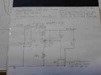
I'm going to try and attach a schematic of such a circuit which I copied out if a lab amplifier which I found.
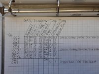
I'll also attach a cheat sheet of all (most) of the relevant info on all the gas regulator tube types.
Wish me luck, and if I am successful, thank me later...
I'm no expert on regulator tubes but I know that using them as a shunt is big the tip of the iceberg. They are really meant to be used in active regulators in combination with other tubes...
I'll repeat, I'm no expert but I know that the real world applications for regulators commonly used them as a voltage reference in a regulator circuit.
I'm going to try and attach a schematic of such a circuit which I copied out if a lab amplifier which I found.
I'll also attach a cheat sheet of all (most) of the relevant info on all the gas regulator tube types.
Wish me luck, and if I am successful, thank me later...
Attachments
When a regulator is used to regulate power pentode screens or beam power tube screens,
the VR voltage will vary if the screen current varies versus signal (which it normally does).
The simple B+, series resistor, VR tube to ground is not able to maintain a constant voltage versus screen current.
Instead, in a typical 3 tube regulator circuit (regulator tube, error amplifier, and Pass/Shunt tube), the load that is in parallel with the VR tube is constant.
That means the voltage across the VR tube is also constant.
And, the amount of current that a Shunt/Pass tube circuit can pass to other circuits is only limited to the tube type, and that part of the circuit, it is not limited to the VR tube's minimum and maximum currents.
Those two regulator circuits have largely different performance.
Take a look at some very old Tektronix Vacuum Tube Oscilloscopes for some examples of regulated supplies, in addition to multiple supplies on the same scope.
I've had good success topping a regulator tube with a single mosfet mu follower. Put a decent sized film cap on its output to ground and a larger cap from the dropping resistor to ground. The voltages between the mosfet's terminals remain nearly constant while driving substantial screen currents.
Yay… finally a voice of experience and reason.
I don't call them 'mu followers', but source followers are eminently (and devilishly simple) pieces of circuit design pattern that deserve wider acceptance. Basically they're 'set-and-forget', and remarkably durable to the spikes and other crâhpola that whiz around power supplies and line voltage.
Any gas 'regulator' should be replaced with the words 'gas discharge voltage reference', and then in the context of a pass-regulator, it all makes more sense.
⋅-⋅-⋅ Just saying, ⋅-⋅-⋅
⋅-=≡ GoatGuy ✓ ≡=-⋅
When a regulator is used to regulate power pentode screens or beam power tube screens,
the VR voltage will vary if the screen current varies versus signal (which it normally does).
The simple B+, series resistor, VR tube to ground is not able to maintain a constant voltage versus screen current.
Can you explain why? Or point to a source in which this is explained?
Looking at the graph on the last page of this datasheet for the ZZ1040 the voltage stays very stable over the range of 5 to 60 mA.
The ZZ1040 has an extra 'ignition' electrode. If used (properly) it will allow shunting the ZZ1040 with as much capacitance as wished without the risk of oscillations.
Attachments
Fair enough. It's a term I see commonly used when a mosfet CCS is employed as a buffered plate load, chosen in this application to avoid the stigma often associated with dedicated SS regulators. The other advantages is by maintaining a constant current through the gas tube presumably its operating life is maximized.I don't call them 'mu followers'...
PFL200,
A common OD3 Gas Discharge Voltage Reference has the following specifications:
1. Operating current, 5mA minimum to 40mA maximum.
2. Nominal operating voltage, 150V.
3. Delta Voltage versus the current varying by 35mA (5mA to 40mA) = 4V
Consider a resistor from a steady B+ voltage to the OD3 plate, and the OD3 cathode to ground.
Les use a series resistor that was calculated to source a Total of 35mA current to the 'OD3 plus the Screen'.
Then, connect a Beam Power tube screen or a Pentode screen that has 3mA quiescent screen current to the junction of the series resistor and OD3 Plate.
When the music transient causes the g1 grid to cathode swing to 0V, the pentode/beam plate swings to +50V, and as a result, the screen current rises to 45mA.
The series resistor from the B+ will be sourcing at least 45mA to the screen, but that causes the voltage to fall far below 150V,
and so the OD3 is extinguished (goes dark).
Does that explain it?
And, just for some more handy information:
From those specs, 4V/35mA change = OD3 dynamic impedance of 114 Ohms.
Last edited:
....
And, just for some more handy information:
From those specs, 4V/35mA change = OD3 dynamic impedance of 114 Ohms.
The dynamic impedance may be negative over some of the operating range.
Plasma is not simple.
6A3sUMMER,
I understood your statement to apply to all regulators, so not only the 0D3.
Your example is chosen so that the lower limit of the 0D3 is exceeded. What if you use the 0D3 with beam power tetrodes or power pentodes of which the screen grid current stays within the limits of the 0D3?
If you would use a ZZ1040 in your example, I think it will not extinguish (certainly not when the "ignition" electrode is also being used) and the voltage would stay stable.
- Home
- Amplifiers
- Tubes / Valves
- How do you use a 0D3 regulator?