pink 150v regs are very dim
100-75v orange, shines strongly like nixie
That's a (I can't help it...) brilliant observation. Its also true. Hydrogen-Argon is the gas, and neither one glows brightly.
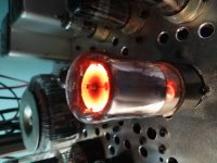
i had only russian types, 75 and 105 were orange, but slightly different in color
brightness was same
SG3S | Tubes Information
SG2S | Tubes Information
SG4S | Tubes Information
brightness was same
SG3S | Tubes Information
SG2S | Tubes Information
SG4S | Tubes Information
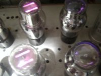
What brand are those VR75s? The only ones i'veever had that glowed purple were VR90s...
Your correct. Didn't have my glasses on what I thought were 75 we actually 90's.
@Burnedfingers did you ever get your 0D3 working? I would like to build a similar power supply. Would you have the schematic to share?
Thanks!
Thanks!
In this video you see a Soviet СГ-2С, straight bulb, in a preamp, and American VR-75 in a power amp, coke bottle. Currents are slightly different, so the brightness is different. But they both glow orange. What glows purple, VT150 and Soviet СГ-4С. Different gases are used for different glow voltages.
Edelweiss-3 2021 production prototypes - YouTube
Edelweiss-3 2021 production prototypes - YouTube

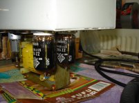
The ZZ1040 (with Magnoval tube base) also glows violet/purple. I use two of them in series to get 200 V for the screens of 2 x EL86 pp in a guitar amplifier. If you give the guitar a good wack at some volume, the brightness 'follows' (diminishes). I didn't make pictures/videos with them working yet.
Somewhere during the build, I made a mistake. I thought I grabbed a 100K resistor (for igniting the ZZ1040's) but it (later...) turned out to be a 470 Ohm resistor. The violet of the color code on this resistor was very dark so I must have thought it was black, and read the color code the wrong way around. At the first trial only one of the ZZ1040's ignited and started to glow like crazy! Very impressive to see, but I knew there was something wrong so switched off right away, found the mistake and corrected it. Luckily that ZZ1040 was still working fine.
Somewhere during the build, I made a mistake. I thought I grabbed a 100K resistor (for igniting the ZZ1040's) but it (later...) turned out to be a 470 Ohm resistor. The violet of the color code on this resistor was very dark so I must have thought it was black, and read the color code the wrong way around. At the first trial only one of the ZZ1040's ignited and started to glow like crazy! Very impressive to see, but I knew there was something wrong so switched off right away, found the mistake and corrected it. Luckily that ZZ1040 was still working fine.
Attachments
Reviving this thread to ask a question - when to use a 0D3 rated 40mA and when to use a 0A2 rated 30mA, both being 150v?
I have a couple of input tubes drawing 8mA each, so total is 16mA.
What i haven't quite grasped is with the 0A2 rated at 30mA, what's the maximum current figure for the tubes it will feed? Is that 30mA max or 30mA minus half of 30mA, i.e. 15mA? The book values actually say 17.5mA rather than 15mA. That's the question I'd like answered.
I have the calculations and with 305v in and a current draw of 16mA plus 17.5mA, total 33.5mA, the calculation gives a resistor of 4.63K which should be around 12W. Equation is voltage drop over total current.
So will the 0A2 handle a tube stage drawing up to 30mA, or if you deduct the 17.5mA will it only handle a tube stage drawing up to 12.5mA?
Perhaps best to review the application of zener diodes for voltage regulation applications, and get a handle on how a particular zener operating current is chosen, and what are the limits to the operating current range (and why). After that then it comes down to being aware of the load's variation in current, and what limits the load may impose or reach.
If the OA2 can operate adequately when its current varies between the limits of (lets say) 5mA to 30mA, then the load can vary between drawing 30mA and 5mA for a setup where the current drawn from the upstream supply is a constant 35mA (which is used to determine the dropper resistor to the OA2 & load). But that design may also need to account for variations in upstream supply voltage, and may also have other resistive loads being supplied, which adds some design complexity.
If the OA2 can operate adequately when its current varies between the limits of (lets say) 5mA to 30mA, then the load can vary between drawing 30mA and 5mA for a setup where the current drawn from the upstream supply is a constant 35mA (which is used to determine the dropper resistor to the OA2 & load). But that design may also need to account for variations in upstream supply voltage, and may also have other resistive loads being supplied, which adds some design complexity.
So will the 0A2 handle a tube stage drawing up to 30mA, or if you deduct the 17.5mA will it only handle a tube stage drawing up to 12.5mA?
The OA2 itself can sink current up to 30mA to maintain 150V at the anode. You don't need to subtract the current of your circuit from that figure. You do need to account for variations in your circuits draw and raw B+ variations so the gas tube is operating with no less than 5 and no more than 30 mA from anode to cathode.
Forgive me, but I still don't understand how this works. Is it possible to simply tell me what is the maximum load a 0A2 can handle in terms of the operating point of the 2 tubes it's feeding? In my case the load is 16mA for the 2 input tubes. So is this OK? And what is the maximum load the 0A2 can handle? At what point does the load become too much and you need to use a 0D3? 30mA or what......? I'm just guessing here, I just don't get it.
I've read through the glow tube instruction sheet on Franks and it doesn't clearly say what load a glow tube can cope with. Is it 30mA for the 0A2 or what? What does this figure refer to if it isn't the load the tube is feeding? Why is this so unclear - we're now on page 12!
And anyway, does a glow tube simply regulate for a fixed voltage or does it also cut down ripple - that's what I need it for, otherwise I'd just use a choke instead.
.
Last edited:
andyjevans,
What can happen in a typical application is this:
There is a voltage dropping resistor from a B+ voltage source to the OA2 or to the OD3.
The junction of the dropping resistor and regulator is connected so that it powers the 2 input tube's plate circuits.
The amplifier is turned on, but the input tubes are cold and so they do not draw any current.
That means that all of the current from the B+ through the dropping resistor goes through the regulator. The current is dependent on the B+ voltage and the dropping resistor Ohms.
Example:
The cold amplifier is turned on.
B+ is 300V
Dropping Resistor is 5357 Ohms.
The regulator ignites, and regulates to 150V.
300V - 150V = 150 across the resistor; and 150V across the regulator.
150V / 5357 Ohms = 0.028A (28 mA).
The regulator draws 28mA.
Now, the input tubes warm up.
They draw 8mA + 8mA = 16mA at 150V
28mA - 16mA for the tubes = 12mA through the regulator
Now, the regulator draws 12mA.
That all is good for an OA2, or for an OD3.
They both draw more than 5 mA (required minimum spec), and less than 30 mA, so they are both operated safely, during power-up, and during the operation of the warmed up amplifier.
Now, suppose the B+ ripple is 10mV (about 3.16mV rms).
An OD3 varies 4V from 5mA to 40mA (35mA change). 4V/0.035A = ~ 114 Ohms
The dynamic resistance of an OD3 is 114 Ohms.
114 / (114 + 5357) = 114 / 5471 = 0.0208, the voltage divider action
3.16mV rms X 0.0208 = 65.8uV.
Is that an improvement on the ripple.
You be the judge.
Does that help you?
Last edited:
Andyjevans, not many references go through the basics of regulator tube operation - the following link has a reasonable description in chapter 18:
https://www.dalmura.com.au/static/Power_supplies_and_amplifiers.pdf
Electronic logic indicates that the sum of the regulator current and the load current must equal the dropper resistor current - with the aim that the dropper resistor current remains constant no matter what the load current does. So if load current was 15mA and regulator current was 15mA then load current could fall to 0mA and regulator current would increase to 30mA (which is still ok). If load current increased to 25mA then regulator current falls to 5mA (which is still ok, but if load current increases more then the regulator may extinguish).
The idle current of the regulator is determined by the idle load current and the dropper resistor value. By raising or lowering the dropper resistance, the regulator current falls or increases - with the aim that you use a dropper resistance that gives you the desired idle currents. You have to know the idle current of the amp for the regulation voltage of the tube - that is your effort to determine.
Yes the OA2 acts to reduce ripple voltage as it shunts the ripple voltage to ground with a relatively low dynamic impedance of a few hundred ohm - which is equivalent to a filter capacitance of about 10uF. But unlike a filter cap, the shunt regulator adjusts its DC bypass current.
Andyjevans,
The OD3 Regulator tries to maintain a voltage of 150V.
From 5mA to 40mA through the tube, it varies by only 4V.
That works for DC current, and it works for Audio Frequency current.
The voltage divider in my previous example is is from 114 Ohms OD3 impedance, versus 5357 Ohms dropping resistor, about 50:1
Good!
If you have a 300V B+, and a dropping resistor to drop that to 150V,
you get 150V / 0.016A = 9375 Ohms.
Keep in mind that capacitive reactance varies versus frequency.
The capacitive reactance of a 10uF capacitor at 120Hz ripple frequency is 133 Ohms.
The ripple reduction is 133 / (133 = 9375) = 133 / 9508 = 0.014
3.16 mV rms x 0.014 = 44uV ripple at 120Hz.
And, there is No regulation of the voltage to the input tubes, for low frequency audio.
In my previous post, the input tube currents can increase from 16mA to (16mA + 5mA), and still have 7mA for the OD3, and it will not extinguish.
If the input tubes need to draw more than an additional 7mA, you need to reduce the dropping resistor, and now the current to the OD3 at power-up will be more than 28mA.
That means the OA2 will likely exceed its 30mA maximum, if only until the input tubes warm up.
Last edited:
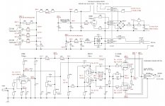
Maybe this example helps. This is the schematic of the amplifier I mentioned in post #110. Just ignore the extra resistors (56K, 100K, 150K) around the ZZ1040's.
The current to the screen grids of the EL86's varies from 4 mA (no signal) to 26 mA (at full power, so 22 mA more than at 'no signal').
The ZZ1040 can sink current between 5 mA and 60 mA. So I chose to set the current through the ZZ1040's for the 'no signal' situation at 36 mA. At full power the remaining current through the ZZ1040's is 36 - 22 = 14 mA, which stays above the minimum current of 5 mA.
As marthy pointed out, the current demand of the two input tubes in your situation stays constant. So you only have to calculate the value for the resistor(s) before the voltage regulator and the two input tubes so that the current running through the voltage regulator stays withing the limits in the datasheet, so somewhere in between those two limiting values. Note that because the current demand of the two input tubes stays contant, the amount of that current doesn't really depend on the current capability of the voltage regulator.
There's one 'but' though. If B+ in your amplifier would come up faster than the two input tubes, than at start-up you would have a short period of time in which the two input tubes don't draw current yet. That current would than be taken by the voltage regulator until the two tubes take that current themselves. In your situation this would mean that you have to stay atleast 16 mA below the maximum current of the voltage regulator you want to use.
Attachments
Thanks guys, much clearer!
I'll take some time to digest this and look at the maths, but I now see that much of this is related to cold start on the input tubes. Very helpful explanations for those unfamiliar with these kind of regs.
I'll take some time to digest this and look at the maths, but I now see that much of this is related to cold start on the input tubes. Very helpful explanations for those unfamiliar with these kind of regs.
https://worldradiohistory.com/Archive-Company-Publications/SYLVANIA NEWS/Sylvania-News-1946.pdf
Some info here I believe page 5 volume 13 no 1
Some info here I believe page 5 volume 13 no 1
- Home
- Amplifiers
- Tubes / Valves
- How do you use a 0D3 regulator?