is 6N3 a low voltage tube or does it happen to work well at low B+ voltages like 6922.
you could use 2 5va torroids one at 5 -6v and one at 22v and voltage double the 44v ( 2 separate windings) from the second one. this would require a new regulation setup for B+ of 130v
you could use 2 5va torroids one at 5 -6v and one at 22v and voltage double the 44v ( 2 separate windings) from the second one. this would require a new regulation setup for B+ of 130v
Last edited:
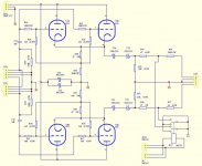
12VAC is about 17V peak. There are 2 voltage doublers (a + and a -) with the diode drops There should be about +33V and -33V, and there are 2 voltage regulators that give about +30V and -30V out. The triodes are wired as cathode followers, so the gain is less than Unity (less than 1). The voltage across the triodes are [60V - (the drop in the self bias resistor + the drop in the cathode load resistor)].
Oops, I just saw that this was not a new posting, just a new comment on one that already has over 130 posts.
Any idea about output impedance and/or maximum output current? I saw earlier that this buffer won't like less than a 10K load... seems pretty poor for a unity gain buffer.
They arrived - each hooked up to its own 12VAC 1A Talema supply. The psu creates 6.25V and +/-32V DC. The tubes glow yellowy-orange and after 30mins, the 7805 is 73degC. With my head amp at full volume, the tube buffer volume at max, and DAC signal connected/muted, there's no background noise. With no signal lines connected, the background noise is a buzzy crispy hum that becomes loud hum with my finger on the volume control. Not surprising. The sound was pretty awful at first - significant distortion - but after 20 mins or so, it started to sound good. So basically, it's a volume control that manages to mask a little of the digital nature of the CD source. The signature is a little warmer and a little brighter - a bit of mid-range cut basically. I haven't tried it with speakers to see how the dynamics and deep bass are affected - I'm using HD650 cans.
I have a question - hope someone can help! - given the AC coupling caps on input and output to block DC, would paralleling both channels AC output be possible? Each tube would be using both channels but as a mono buffer, so inputs and outputs are tied together. I know that for an op amp, a small series resistor on output would be necessary (say 47R) - does that also hold true for tubes? It's another way of asking about output impedance I guess...
I am also struggling to find a datasheet for the 6N3 tube - little help?
Thank you!
Last edited:
I found two in Russian and Wikipedia has only this info in English: Uf = 6.3 V, If = 350 mA, µ = 36, Ia = 7.7 mA, S = 4.9 mA/V, Pa = 1.5 W. I think I need to know plate resistance?
This is going to take some time to work out so if anyone already knows about paralleling tube outputs (like an amp47 op amp design), please save me some time.... thank you.
EDIT the attached "6N2" chinese datasheet has the chinese for 3 (3 horizontal parallel lines) but I guess this refers to something else, not type.
Attachments
Last edited:
6N3P was never intended to be used in audio. Contrary, it was used in FM frequency converters, due to low capacitance and non-linear transfer curves. Also, as you can see from the graphs, at 0V and 1 mA minimal anode voltage is about 30V, with zero grid bias.
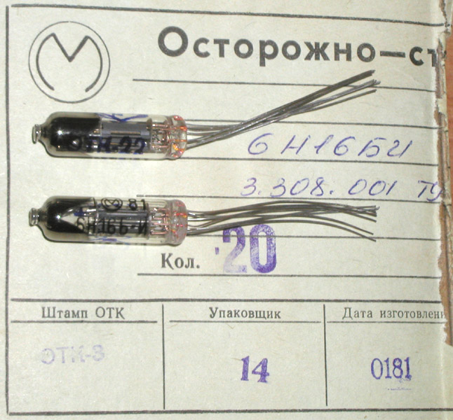
If you want a seriously good tube for audio and low voltage, better find something like 6N16B.
If you want a seriously good tube for audio and low voltage, better find something like 6N16B.
Last edited:
What do you mean "Compatible"? It is a better tube for audio, and works better on low voltage than 6N3 that is not linear tube; 6N3 is used in Chinese kits because they don't know what do do with the stash.
6N16B is almost like a miniature 6SN7, and can be soldered directly on a PCB.
6N16B is almost like a miniature 6SN7, and can be soldered directly on a PCB.
Sure, but I'm not interested in doing that. I'm interested in paralleling buffer outputs of the design that is described in this thread, not something else.
I found the Spice SIM for 6N3 / 5670 etc - thanks to the folks on this thread. https://www.diyaudio.com/forums/tubes-valves/243950-vacuum-tube-spice-models-154.html#post5259089
I found the Spice SIM for 6N3 / 5670 etc - thanks to the folks on this thread. https://www.diyaudio.com/forums/tubes-valves/243950-vacuum-tube-spice-models-154.html#post5259089
What value of current drain? A specific fet would be helpful : -) I've got some constant current diodes but I doubt I have the right value. Let me know which one you use and i'll order it.
There are many things to try, but for now I'm really focused on paralleling... I reckon 100R on the output of each will make load sharing work but will limit the benefits. I'm hoping to optimise the value of R.
There are many things to try, but for now I'm really focused on paralleling... I reckon 100R on the output of each will make load sharing work but will limit the benefits. I'm hoping to optimise the value of R.
Last edited:
Parallel 6n3 for headphone amp. But no low anode voltage(200v).
Yes, as cathode followers with 200V B+ source they are fine.
Parallel 6n3 for headphone amp. But no low anode voltage(200v).
And super E caps - nice
") Thank you so much for sharing that!
Thank you so much for sharing that! 
Last edited:
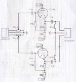
Does anyone know if the two channels should measure roughly the same if they have the same power supply, same resistor values etc.? In other words, should there be a considerable difference between two channels of the same tube? I have two of these buffers, which is four channels, and for both buffers, the voltages across the resistors at the cathode are significantly different. For example, across the 470R connected to the cathode, the two left channels on each buffer both show 0.8V and the right channels are 0.2V and 0.35V. Is this a common problem with made in China tubes?
Attachments
Last edited:
Hugh Jazz,
* 1 That buffer may be good for very small signals into a very high impedance load.
Otherwise, it will have lots of distortion.
The current is very low, and the grids are 0.8V or less away from the cathode (some tubes will have grid current, and/or 'grid leak bias' voltage on the grid).
The tube with only 0.2V across the 470 Ohm resistor has very little voltage across it.
Plate: +30V. Cathode: -30V +5.1V + 0.2V = -24.7V
Vpk = 54.7V
The tube with only 0.8V across the 470 Ohm resistor has even less voltage across it.
Plate: +30V. Cathode: -30V +20.4V + 0.8V = -8.8V
Vpk = 38.8V
I do not think you can expect those tubes to operate very well with only 39V across them.
Try some other tubes of the same type, and see if the match is better. But even if the voltages match very well, refer to * 1 above.
Thanks for the help - much appreciated!
I will definitely try a pair of 5670 - not least because there is a datasheet in English for them
I think the easiest way to bump up the voltages is to use a 15-0 or higher trafo - just need to keep voltages under 63V incl ripple for the caps' sake, with a target of 100V across the tube. The 7805 that supplies the filament will get very hot so I'll need to fix that - perhaps use an smps buck before it to drop voltage without significant heat.
Last edited:
You could also try a 6DJ8 instead as they tend to work better with lower voltages...
https://www.ebay.ca/itm/1pc-gold-pl...h=item2efd181441:g:aUIAAOSwoudW178m:rk:5:pf:0
https://www.ebay.ca/itm/1pc-gold-pl...h=item2efd181441:g:aUIAAOSwoudW178m:rk:5:pf:0
Thanks for that - I think I found the same adapter available locally. About half price from EBay.
?????????ECC88 6DJ8 6922?5670 6n3-???
An English datasheet is easy to find and they are priced similarly to 5670 too.
?????????ECC88 6DJ8 6922?5670 6n3-???
An English datasheet is easy to find and they are priced similarly to 5670 too.
Last edited:
- Home
- Amplifiers
- Tubes / Valves
- 6N3 Tube Preamp with DC-DC converter