Sheldon, Yes, you can connect up a normal triode stage, and feed the anode with the emitter of an NPN. (NPN-base to fixed dc voltage, NPN-collector to resistor-to-B+).
This would just be a series cascode - but the NPN gives much better performance, and sound, than a triode in the upstairs position.
I can't think of any advantages for a summed output.... have you drawn it out, to see if it works, at least from dc-current position?
The shunt cascode has very high open-loop gain - higher than any normal valve stage, even compared with pentodes. So you can usually get what you need with the basic circuit.
One must be careful with adding parts to a high gain circuit - it may make things more difficult for stability.
Shunt cascode MOSFET driver?
Hello again Rod
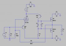
I was wondering about DC coupling of your shunt cascode circuit to a simple follower - say a simple MOSFET stage. I've sketched my idea loosely.
I can't seem to figure out how to accomplish this AND maintain output DC offset. Wondering about a DC servo connected to Q2 base, via an additional NPN transistor, perhaps? I'll try and sketch this out tonight.
Thoughts? Was this also a problem when you attempted to DC couple to an EL84?
Regards
Sheldon
Hello again Rod
I was wondering about DC coupling of your shunt cascode circuit to a simple follower - say a simple MOSFET stage. I've sketched my idea loosely.
I can't seem to figure out how to accomplish this AND maintain output DC offset. Wondering about a DC servo connected to Q2 base, via an additional NPN transistor, perhaps? I'll try and sketch this out tonight.
Thoughts? Was this also a problem when you attempted to DC couple to an EL84?
Regards
Sheldon
Attachments
Last edited:
Yes, Sheldon, I have considered this exact idea...
Clear choice for the outputs would be the SEMELAB Lateral MOS in TO-247:
N-channel BUZ900P
BUZ900P - SEMELAB - MOSFET, N, TO-247 | Farnell UK
P-ch BUZ905P
BUZ905P - SEMELAB - P CH MOSFET, -160V, -8A, TO-247 | Farnell UK
This kind of stage can actually be run open-loop, if you are interested in that.
some experimenters in Japan have characterised them like that, I'll try to look it up again when I get a minute.
Run them at 100mA idle in every case, and take advantage of the zero-TC (idle current stable with temperature).
As for dc coupling, a servo would be mandatory, since the offsets can't be guaranteed without. I would prefer a small coupling cap and an emitter follower to drive the FETs - the input capacitance of most power FETs is too high to drive directly, in any design.
Hello again, Rod
Agree completely on MOSFET choices. I haven't included full bias arrangement/gate stoppers etc for the purpose of my query.
Initially I was concerned about MOSFET drive capacitances also, and I had included a cathode follower between the shunt cascode and the outputs. Actually a triode-connected 5763, of which I own plenty. I took this out based on what you'd written about the shunt cascode's ability to drive impedances down to around 1k, thinking it may be overkill. But this is easily added again, so no worry.
The reason I want to run closed loop, is to implement Rod Elliot's mixed-mode feedback - see Variable Amplifier Impedance You "Rods" are all very smart and generous with your time and knowledge")
I'm concerned about global feedback with capacitative coupling to the MOSFETS, in terms o loop stability. I simply don't have broad enough knowledge to be sure I won't encounter a problem I don't know how to solve.
Which is much the same for the offset servo, actually...
Rgds
Sheldon
Agree completely on MOSFET choices. I haven't included full bias arrangement/gate stoppers etc for the purpose of my query.
Initially I was concerned about MOSFET drive capacitances also, and I had included a cathode follower between the shunt cascode and the outputs. Actually a triode-connected 5763, of which I own plenty. I took this out based on what you'd written about the shunt cascode's ability to drive impedances down to around 1k, thinking it may be overkill. But this is easily added again, so no worry.
The reason I want to run closed loop, is to implement Rod Elliot's mixed-mode feedback - see Variable Amplifier Impedance You "Rods" are all very smart and generous with your time and knowledge
I'm concerned about global feedback with capacitative coupling to the MOSFETS, in terms o loop stability. I simply don't have broad enough knowledge to be sure I won't encounter a problem I don't know how to solve.
Which is much the same for the offset servo, actually...
Rgds
Sheldon
Closed loop stability with shunt cascode is another easy step - especially since you're already loading the circuit into LTSPICE.
Just place a cap in parallel with the load resistor to effect frequency compensation. you can use LTSPICE to check the overall frequency response, and examine phase.
The stability of the triode requires ferrite beads in anode, and PNP emitter, and compact construction.
When the triode oscillates, it will probably be at 300kHz-4MHz, and if the closed-loop stability fails, the oscillation will probably be below 100kHz - as a rough troubleshooting guide.
Don't worry about the cap-coupling: this should not interfere with stability.
You can build the triode stage in open-loop mode to begin with, and check it does not oscillate. Then you are ready to add the power stage.
Rod,
I have read the post in Bartola Valves about a variation of your circuit. This variation includes a darlington instead only a PNP transistor. This circuit has a RLoad of 27k (if i remember correctly).
My question is about output impedance. It seems that Zout is approxymatelly the value of RL.
It seems some high Zout for driving a 300B. It isn't?
Regards,
Luis.
Hi Luis,
Yes, I have tried darlington versions, and expected the distortion to be lower. But there is very little difference, and I am back to using singles again.
Yes Zout is RL, so it should not be any higher than 27K. But that works fine for most 300B designs, since the full-power bandwidth is still above 20kHz. The 300B should not really be driven into A2 (grid positive) in normal use - especially for expensive new tubes! But if you do want to drive harder, adding a follower is very easy to do.
I'm still working on the 300B driver, occasionally - and hope to produce a version that gives very low dc drift - to allow dc-coupled designs - this might be the best solution for 300Bs.
Thanks for your response.
As I see, the problem is not to "drive hard" by own intention. I believe that in music reproduction, with a huge peaks above average value, probably we go to positive grid in some cases. And I don't know what the matter is when we get positive grid for a moment.
I think that probably, the problem is for Shunt Cascode, not for 300B, and a nasty distortion would be get into grid of 300B.
I'm not sure.
Buffering with a follower this problem is minimized?
When the shunt cascode is biased properly, the grid will not drive positive, or only a very little. I use the shunt cascode like this every day for 12 years.... the distortion is very low.
But some designs are different, and if you need hard driving, a follower will eliminate that problem completely.... but please be careful, and consider the peak anode current of the 300B, and if it will be happy with higher current: some manufacturers warn against it.
But some designs are different, and if you need hard driving, a follower will eliminate that problem completely.... but please be careful, and consider the peak anode current of the 300B, and if it will be happy with higher current: some manufacturers warn against it.
I should mention that the biggest problem of distortion is caused by the grid coupling capacitor. If the grid 300B conducts, the grid cap charges, and polarises the capacitor. This polarizing voltage changes the 300B bias - and causes 'blocking distortion'.
This is a risk for any 300B driver with capacitor coupling.
It can be solved again with a dc-coupled follower, biased to the correct voltage. you can ac-couple to the follower input (base, gate, grid).
A solution like this may find its way into my driver PCB soon.
This is a risk for any 300B driver with capacitor coupling.
It can be solved again with a dc-coupled follower, biased to the correct voltage. you can ac-couple to the follower input (base, gate, grid).
A solution like this may find its way into my driver PCB soon.
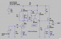
You are right, we can design the voltage swing for the cascode for never surpass to positive grid, only problem here is, when this happens, we get a hard clipping at output of shunt cascode...
At least it is what I see in my simulations.
Attach my circuit simulation with hard clipping when we go above 165 Vpeak to peak.
I will go for PCBs, but I have some doubts about oscillations.
I hate to see a high gm tube as 5842 oscillating...
Have you some advices about?
Regards,
Luis.
At least it is what I see in my simulations.
Attach my circuit simulation with hard clipping when we go above 165 Vpeak to peak.
I will go for PCBs, but I have some doubts about oscillations.
I hate to see a high gm tube as 5842 oscillating...
Have you some advices about?
Regards,
Luis.
Attachments
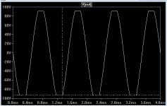
When the output of the grid-driver reaches the maximum positive voltage (=anode voltage of the driver tube) then we see a sudden stop in the output voltage. But that is not the whole story! The current does NOT suddenly increase - it continues to rise at gm/Vin. The output current remains under full control at all times!
For this reason, the shunt cascode driver recovers immediately from clipping, especially when it is biased to avoid driving the 300B grid above zero. The end result is that clipping is very difficult to hear, so long as it is just tall peak being clipped.
Now, when you add the FET follower, the voltage saturates in the same way, but the current is unlimited. The grid capacitor will charge very quickly, and we will get very bad blocking distortion.
The alternative follower circuit is more successful:
1. connect the output to the FET gate with CR network 10nF/1MΩ.
2. Bias the 1MΩ with negative voltage (for fixed bias) or Ground (autobias)
3. DC-couple the FET Source to the 300B grid
4. Use a 600V FET with low Cre, and ±30V durability for Vgs.
5. Apply 2x 22V BZX55C22 back-to-back zeners across FET G→S.
This circuit suffers no blocking distortion up to (22V - Vgs) above the 300B grid voltage, but now you have no current limit into the 300B grid. You can try this circuit out on cheap 300Bs (if such a thing exists) but the current limiting and simplicity of the circuit without a follower is a safer and better solution, IMHO.
It will be improved again, with the dc stabilisation, and the possibility of the dc-coupled output (these features are not completed yet).
Folded with a DC coupling to the output tube
reading on Åle Bartola's website, I pondered on the circuit.
I decided to try a choke load for the folded cascode, and this gives a neat DC low level on the output - just the Rdc x current, in my case about 1k2 x 10 mA.
Having that - there can now be DC coupling to the output tube. Just raise the cathode resistor a bit. It only works with a resistor parallel (sweep - frequency wise). Strange, because a chokeloaded anode needs no resistor. (in simulation . . .)
The sine will now swing from positive to negative. for example -36 to + 54 grid volts. Output FFT looks promising. Grid swing is +54 to -36V with 4V in.


OK OK I did add a feedback loop which works ! ! can be done because it is without any coupling cap.
The same result is reached with a CCS with a bias of -80V and ensuring the grid is at the same level as the first experiment.
any suggestions and inspiring feedback? Here quick 6SN7 tube.
reading on Åle Bartola's website, I pondered on the circuit.
I decided to try a choke load for the folded cascode, and this gives a neat DC low level on the output - just the Rdc x current, in my case about 1k2 x 10 mA.
Having that - there can now be DC coupling to the output tube. Just raise the cathode resistor a bit. It only works with a resistor parallel (sweep - frequency wise). Strange, because a chokeloaded anode needs no resistor. (in simulation . . .)
The sine will now swing from positive to negative. for example -36 to + 54 grid volts. Output FFT looks promising. Grid swing is +54 to -36V with 4V in.
OK OK I did add a feedback loop which works ! ! can be done because it is without any coupling cap.
The same result is reached with a CCS with a bias of -80V and ensuring the grid is at the same level as the first experiment.
any suggestions and inspiring feedback? Here quick 6SN7 tube.
Member
Joined 2009
Paid Member
This folded cascode arrangement always intrigued me but so far I've not built one. It looks to me as if it's a technique to 'pentode wire a triode' as opposed to the more popular 'triode wire a pentode'. The base of the transistor is somewhat equivalent to the screen grid which is why you have to feed it with a clean voltage. The transistor pins the anode potential of the triode so that the anode potential no longer has the full signal voltage with which to influence the current flow in the tube. Just like a pentode in behaviour. And it gives two other benefits, just like a pentode, in that the miller capacitance of the input tube is greatly reduced and you get more voltage gain. Like a pentode it also has reduced PSRR. As a transistor requires a Vbe voltage signal to generate a signal at the collector the signal applied to it will traverse the transistor load line so a small but potentially inaudible part of the transistor characteristic is part of the operation. You do avoid the microphonics of a sesitive pentode though. The load-line for the triode is nearly a vertical line since the anode potential is fixed which means the usual sense of linearity and sound from the triode goes out of the window and you are into unchartered territory when it comes to picking the best triode for a circuit like this - I would expect though that a triode that is linear when used as a triode is also a good starting point when used wired up like a pentode.
Last edited:
This folded cascode arrangement always intrigued me . .
Like a pentode it also has reduced PSRR.
As I understand it this folded arrangement refers the anode to ground and hence has an 'infinite' PSRR.
As I understand it this folded arrangement refers the anode to ground and hence has an 'infinite' PSRR.
PSRR in a Shunt Cascode (the version in my drawings, at least!) has very high PSRR, but it does depend on the current-source.
Further, having the input AND the output referred to ground gives excellent immunity from conducted and radiated noise emissions.
Happily, using the standard depletion-FET circuit (pair of DN2540, cascoded) is all you need to get superb performance.
Al, have you constructed the circuit?
General thoughts:
Shunt Cascode stages work best with high-quality, small triodes (or triode-connected pentodes) with a minimum working gm of 10mA/V, or better still, 20 to 30mA/V.
I don't expect good results with 6SN7, sad to say. Octals, and DHTs are not recommended for Shunt Cascode - it imposes a vertical load-line on the valve, and this just suits high-gm valves better. Run a ruler over the (measured) triode curves and see.
Low gm like the 2-3mA/V of 6SN7 means not enough open-loop gain to give useful headroom for feedback purposes.
Shunt Cascode can easily give open-loop gain of 400 from one triode. You can achieve excellent linearistion with a cathode resistor, unbypassed. So, yes, you can get rid of an electrolytic bypass cap, without any further trade-off, as part of the deal.
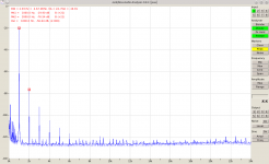
For example, the Russian 6Э5П (6E5P) gives 30mA/V at 30mA, and you can linearise this down to 7mA/V with a 110Ω Rk. The gain is still 44dB (>150) with a 22K load resistor, so you can drive a 300B with only one stage, and very low distortion at 150V p-p.
With this kind of performance, I don't see any advantage in closing the loop around the whole driver - unless you want to linearise some other stage or device in the loop. Now, that is something interesting that I will look at when I get a moment.
Hello Jaap,
I did a batch, but they all found homes! They will be back in stock gain soon...
Measurement attached for the 6Э5П driver for 300B, at 150V p-p
from:
Rod Coleman Shunt Cascode - Power Tube Driver
.
I did a batch, but they all found homes! They will be back in stock gain soon...
Measurement attached for the 6Э5П driver for 300B, at 150V p-p
from:
Rod Coleman Shunt Cascode - Power Tube Driver
.
Attachments
Member
Joined 2009
Paid Member
As I understand it this folded arrangement refers the anode to ground and hence has an 'infinite' PSRR.
the limitation is power rail noise injection at the base of the cascode device.
the ‘fix’ is a more complex circuit. of course you can add a current source to a pentode to improve psrr too.
like any cascode, the circuit has the characteristics of a pentode and what you get is gain = gm x load impedance. Linearity depends on the gm curve, not mu.
Last edited:
- Status
- This old topic is closed. If you want to reopen this topic, contact a moderator using the "Report Post" button.
- Home
- Amplifiers
- Tubes / Valves
- Shunt Cascode Power Valve Driver