revintage said:What about this one with a Slagle bifilar 1:1 IT?

With some tweaking one might even get away with only one PSU, feeding the driver from the 6080 B+.
I happen to have a 1:1 IT from somebody somewhere I will try it once done with the last tweak just previously posted.
Ok sorry for not getting back sooner to much going on with holidays up and coming.
I now have 135vdc (+/- 2vdc) on 6080's (Yes I changed to 6080's).
I changed the original design with the two 40 ohm cathode resistors in series to be the following:
1. The cathode resistor between the tied cathodes of the 6080's and the bottom of the grid resistor is now 34 ohms.
2. The cathode resistor from bottom of grid resistor to ground is now 30 ohms.
3. This now gives me a total series resistance in the cathode per side of 64 ohms instead of 80 ohms.
With all that said I get 48vdc (+/- 0.5vdc) at the tied cathodes of the 6080's. This gives me 741mA per side which is almost the desired design max of 125mA per triode or 250mA per tube.
No listening impressions yet as carrying this thing over to my listen area takes a bit of planning now that i modified the power supply (Larger 10uf input cap, all PS resistors now mounted on large heat sink since one let go). So I will get back to you later today or tomorrow on that.
revintage said:My guess is you will get 0,5W, 5%THD, 8ohms.
Hey Lars if you get a moment could psot the formula you are using to determine this as I can not come up with a similar number and i am sure i am missing something somewhere. Thanks
revintage said:Used LTSpice to find swing, then Urms^2*Rload. Gives quite predictible figures.
Not familiar with LTspice so please forgive me if I ask to much.
Are you saying you took say the expected input voltage (+/- 2v) x it by the swing of the 6SN7 and then used the above formula?
Because I used P=VI and came to 1.5w.
Thx
Did a quick calculation of gain in your 6080s and cameup with 0,2x. This because the load(8//64ohms) is so much lower than Zout at ca 25ohm.
To make good calculation you must also involve UaIa-curves.
But they should give the same result as Spice, as the mathematical models are based on the same UaIa-curves.
To make good calculation you must also involve UaIa-curves.
But they should give the same result as Spice, as the mathematical models are based on the same UaIa-curves.
Ok raised voltage on 6as7 plates and getting 750mA per side just did a listening test and she sounds very nice on an old pair of Scott 3 way speakers (Test Beds) that are 90db. Distortion is gone, and volume level is very nice so if these really are .5 watt per channel then i am a little shocked. Still need to work out some issues with the power supply as it keeps killing 50w aluminum housed resistors due to way to much voltage drop at to high an amperage but that is next.
I plan to keep this test bed together for now and work out the PS issues and move onto the next OTL so i can compare the two.
I will post next one here as well. I am pouring over some reasonly down loaded schematics from some Japanese sites as well as considering what was posted here.
MAYBE A TECHNICS 20A CLONE WILL BE NEXT!
Anyone have any 50h-b28's available or know a good substitute?
Thanks,
Nice to hear(!) her playing music!
About the resistors I think your next move should be a CCS as this will raise output power a notch!
Good luck with next project🙂 !
About the resistors I think your next move should be a CCS as this will raise output power a notch!
Good luck with next project🙂 !
Sorry made one error the tube I was wonder if anyone has info on is the 50hb26 not 28. Thanks Really need sub
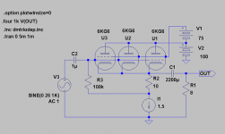
Why go for these odd tubes? Go for 6KG6/EL519!
I have a box with at least fifty PL509/519.
Five per channel would be just about enough to keep a smile on my face until the electricity bill hits the mailbox...

With 5/channel it will set you back less than 1SEK/hour.
With 5 you will get clip at over 12W/8ohm at 5% THD with a DF at less than 2 w/o NFB! The sim indicates at least 3W at 1% THD, still w/o NFB.
With 5 you will get clip at over 12W/8ohm at 5% THD with a DF at less than 2 w/o NFB! The sim indicates at least 3W at 1% THD, still w/o NFB.
Prices new/nos for different tubes
$25/tube EL519
$38/tube EL509
$8/tube 6AS7
$6/tube 50hb26
$6/tube 17KV6A
$8/tube 6336
Enough said.
$25/tube EL519
$38/tube EL509
$8/tube 6AS7
$6/tube 50hb26
$6/tube 17KV6A
$8/tube 6336
Enough said.

Hello,
I'm very interested in this forum and also I was amazed by:
http://www.transcendentsound.com/singleended.htm
(never seen, only red about!!)
Your schematic is also usable with 6c19 that is about half 6080?
You can find 6c19 on Ebay for about 1,5eur.
I'l be great if you try to modificate the schematic fo this tube.
I'd like to experiment this configuration.
Sorry for my bad english.
Ciao
Guglielmo
Italy
astouffer said:
Where are you buying 6336s for $8? How about a 6C33C?
checked ebay and it was buy now $8 but that tube is not for me.
- Status
- Not open for further replies.
- Home
- Amplifiers
- Tubes / Valves
- 6as7/6080 Se Otl