This may have been covered before, but my search was useless.
Last night I was discussing Ultralinear output stages with a friend of mine and he mentioned using zener diodes to drop the voltage on the screen. This could be important if driving a vintage 6550 or perhaps a sweep tube. This reminded me of an old article in Sound Practices which I looked up:
from "The Classic Williamson 1993 Style" by Bill Kleronomos (Sound Practices #4)
"An unusual method of applying active screen voltages to the tubes is used. Instead of the usual dropping resistors, I used a set of 5 Watt Zener Diodes for special benefits : screen voltage is always held at or below manufacturer's recommended value regardless of screen current. Distortion products are materially lower because of the stiffer screen supply provided by Zener regulation - this is especially true for the EL-34 pentode with its wider ranging screen current than the usual beam power tubes. And less screen voltage requires less bias voltage and therefore less peak signal voltage from the driver at max. output. Bench tests with EL-34s and 6550s in the output sockets confirmed an approx. 20% reduction in THD when the original dropping resistors were replaced by Zeners."
Thoughts? I was going to give this a try on my current amplifier I've been playing with. I haven't seen anyone else use zeners in the UL taps like this.
Attachments
That is incorrect. The screen will not be regulated except, as Wavebourn says, wrt the plate (and B+). That is not a stiiff screen supply unless B+ itself is regulated.Distortion products are materially lower because of the stiffer screen supply provided by Zener regulation
I am intrigued by the idea.
Personally, I would think that the zener noise voltage would be such a small magnitude compared to the power supply voltage that I would not expect it to be a big problem. However, you could always build one bypassed and one not and then use your ears or test equipment tell you if there is a difference.
I'll eventually try it, but my project is coming along too slowly to promise anything in the near future.
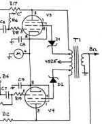
I did some experiments along these lines when I was torturing some sweep tubes at plate voltages that would melt the screen grid. The results were promising but there is only so much to be gained. If you use too big of a zener the G2 voltage can approach zero on low going plate voltage excursions. For those who are sandophobic a gas regulator tube can be used. The photo below shows a 6CD6 with an 0B2 between the UL tap and the screen grid. Do not copy my unique breadboarding method. I think that an 0A2 migh have been more suited because when I really cranked it the 0B2 would extinguish on peaks causing some really rude distortion.
Attachments
last night I soldered in a 25V/5W zener and gave it a quick listen... everything sounded 'bout the same. Didn't have time to do any measuring with the rest of the family down with the flu.
This is on a complete test rig single mono amp using a single Shuguang EL156 running on outboard regulators.
This is on a complete test rig single mono amp using a single Shuguang EL156 running on outboard regulators.
Hi, I would like to drop 100V on the screens of a PP UL EL34 amp I'm finishing.
B+ is 500V and UL is 23%, so instead of having plates from 500 to 70V and screens from 500 to 400V, I would like to have screens from 400 to 300V.
Looking at a classical zener I/V plot:
and screen current plots of EL34, am I right that it is preferred to have a resistor to ground to ensure 1mA through the zener, to keep the 100V stable?
As for the wattage, am I right saying that 5W is ok?
At 100V it's 50 mA for screens.
Thanks
B+ is 500V and UL is 23%, so instead of having plates from 500 to 70V and screens from 500 to 400V, I would like to have screens from 400 to 300V.
Looking at a classical zener I/V plot:
An externally hosted image should be here but it was not working when we last tested it.
and screen current plots of EL34, am I right that it is preferred to have a resistor to ground to ensure 1mA through the zener, to keep the 100V stable?
As for the wattage, am I right saying that 5W is ok?
At 100V it's 50 mA for screens.
Thanks
The idea with zeners in g2 is still UL but keeping the g2 under the maximum permitted voltage. But then the maximum voltage swing of g2 is reduced by the zener voltage, which will result in lower output power.
g2 voltage has to be higher than cathode voltage at maximum positive drive (max. g1 voltage and max. cathode current). There should be also some margin between g2 and k.
g2 voltage has to be higher than cathode voltage at maximum positive drive (max. g1 voltage and max. cathode current). There should be also some margin between g2 and k.
I've never seen anywhere in any reliable descriptions of pentodes or beam tubes the requirement to assure the screen is operated at a lower voltage than the plate. Looks to me the belief is unique to many here on DIY. Where did this strange belief originate? None of texts I've got on EE from that era make mention of the screen volts issue. And I don't recall it was ever an issue in the 50s & 60s when toob amps were at their zenith.")
I've never seen anywhere in any reliable descriptions of pentodes or beam tubes the requirement to assure the screen is operated at a lower voltage than the plate.
Below is an excerpt of a 2004 interview of Scott Frankland, the "F" of MFA fame. It matches my own experience about high screen voltage.
Pappas: Why do tubes blow up?
Frankland: Well, they don't actually blow up, they just arc-over and die.
Pappas: For no good reason?
Frankland: The usual cause is excessive screen voltage.
Pappas: Can anything be can be done about that?
Frankland: Manufacturers can start respecting the limits published in the tube manuals. This respecting of the manuals was common during the golden era.
Pappas: But aren't some brands more rugged than others?
Frankland: True. There is a great variation among tubes in this respect. But there is also a great deal of consistency in the tube manuals with respect to operating voltages. So it's largely empirical. The problem is that if we design our amp with a rugged tube, operating at the edge of its capability, what do we do when that tube is no longer available?
Pappas: It would almost make more sense to design tube amps to operate with the lowest common denominator.
Its real use is to drop the screen voltage if you want to run the plates higher but are limited by the screen. Note you are increasing the amount of UL contribution but you could use a 100v zener say and run a 6550 plate at higher voltage to get more output power if you wish.
See an example of 807 in tetrode mode.I've never seen anywhere in any reliable descriptions of pentodes or beam tubes the requirement to assure the screen is operated at a lower voltage than the plate. Looks to me the belief is unique to many here on DIY. Where did this strange belief originate? None of texts I've got on EE from that era make mention of the screen volts issue. And I don't recall it was ever an issue in the 50s & 60s when toob amps were at their zenith.
Attachments
...But then the maximum voltage swing of g2 is reduced by the zener voltage...
Why? The Zener lowers the dc bias at g2, it does not reduce the ac signal amplitude.
...am I right that it is preferred to have a resistor to ground to ensure 1mA through the zener, to keep the 100V stable?
You want to assure that the Zener is operated in a flat portion of its curve at all times. i.e. its Vf stays constant. If you need to push additional current through it, so be it. You can also look at other methods, e.g. using a different Zener or a series string of lower voltage Zeners, whatever works to give you the characteristic you want.
Keep in mind you normally have a resistor in series with the screen, so when you draw additional current you affect the (variable) drop there as well.
It does not. But at the condition when Vg2 - V(ACpeak) gets close to Vk, the tube will cutoff. If Vg2 is lower, the AC swing can't be as high as with higher Vg2. There is less headroom for the AC swing in the negative direction.Why? The Zener lowers the dc bias at g2, it does not reduce the ac signal amplitude.
I see now what you mean. Yes, he has to make sure he conforms to the available headroom. That's always part of the design process. But we don't know if that represents a real limitation, maybe he doesn't need all the headroom available. And if it really is a limitation, he can always decide to go to a 50V Zener or whatever he needs. I don't see this as a major issue.
But I also don't know the reason for his desire to lower the g2 bias on an EL34 in UL, so....
But I also don't know the reason for his desire to lower the g2 bias on an EL34 in UL, so....
- Home
- Amplifiers
- Tubes / Valves
- Ultralinear with zener on the screen