Hi everyone,
I am finally starting my SSE build, I got the pcb from George awhile back, 4-5yrs ago if my memory serves me right. Then life happened, moved to a new country, moved houses etc etc. Anyway, I am asking for assistance on my build and would appreciate any help I can get.
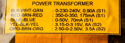
First question is about the power transformer, I got this PT which doesn't have the standard wire color coding used by Edcor or Hammond. It also has extra wires which I am not clearly sure where to hook up in the pcb or if they need be at all. Attached is a photo of the label underneath the PT.
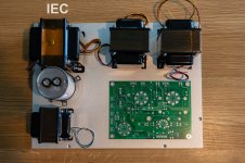
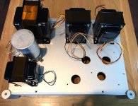
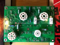
Second question is about layout, attached is the photo of my mock up. the silver plate is the actual top plate of the chassis. Pls let me know if this is ok or if I need to move anything.
Thanks in advance.
I am finally starting my SSE build, I got the pcb from George awhile back, 4-5yrs ago if my memory serves me right. Then life happened, moved to a new country, moved houses etc etc. Anyway, I am asking for assistance on my build and would appreciate any help I can get.
First question is about the power transformer, I got this PT which doesn't have the standard wire color coding used by Edcor or Hammond. It also has extra wires which I am not clearly sure where to hook up in the pcb or if they need be at all. Attached is a photo of the label underneath the PT.
Second question is about layout, attached is the photo of my mock up. the silver plate is the actual top plate of the chassis. Pls let me know if this is ok or if I need to move anything.
Thanks in advance.
Attachments
Last edited:
The transformer ID should be no problem, each lead/color is identified
with its associated voltage on the label.
black white green = 0 230 240
Choose either white OR green for your line voltage.
black/white for 230V OR black/green for 240V
insulate and don't use the other lead in each case
red brown red = 350 0 350
which is red/red 700V with brown CT.
yellow black yellow
which is yellow/yellow 6.3V with black CT
orange brown orange
which is orange/orange 5V with brown CT
Last edited:
rayma, thank you for this detailed response. so just insulate the extra wires which will not be used is the basic guideline, right? in line with that, do I just use electrical tape or shrink tubing for the exposed ends?
I appreciate the help.
I appreciate the help.
The transformer ID should be no problem, each lead/color is identified
with its associated voltage on the label.
black white green = 0 230 240
Choose either white OR green for your line voltage.
black/white for 230V OR black/green for 240V
insulate and don't use the other lead in each case
red brown red = 350 0 350
which is red/red 700V with brown CT.
yellow black yellow
which is yellow/yellow 6.3V with black CT
orange brown orange
which is orange/orange 5V with brown CT
great! can proceed with this layout now. thanks ")
layout looks good. same positions i have everything in on my tse
rayma, thank you for this detailed response. so just insulate the extra wires which will not be used is the basic guideline, right? in line with that, do I just use electrical tape or shrink tubing for the exposed ends?
I would do both. First cut off any exposed wire. Then tape over the end. Then heat shrink over the tape.
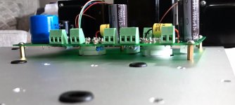
This is a choke input filter (rectifier -> choke -> capacitor)?
Sounds like they want you to connect the start/in lead to the rectifier,
and the finish/out lead to the first capacitor.
Electrical tape is actually not recommended for use in electrical circuits,
but when used underneath properly installed heat shrink tubing, it's ok.
The heat shrink tubing should extend (empty) for a bit beyond the end of the wire.
Last edited:
yes, looking at the schematic and traces on the board this is a choke input filter with one end connected to the rectifier and the other to a capacitor.
Is there a better way to insulate these unused wires, is there an attachment you can buy to put at the end of each lead or am i overthinking this?
thanks again
This is a choke input filter (rectifier -> choke -> capacitor)?
Sounds like they want you to connect the start/in lead to the rectifier,
and the finish/out lead to the first capacitor.
Is there a better way to insulate these unused wires, is there an attachment you can buy to put at the end of each lead or am i overthinking this?
thanks again
Electrical tape is actually not recommended for use in electrical circuits,
but when used underneath properly installed heat shrink tubing, it's ok.
The heat shrink tubing should extend (empty) for a bit beyond the end of the wire.
For small gauge "flying" wires like these, there's no perfect option.
But as before, cut the exposed wire off, tape over the end, and use heat shrink.
Sometimes for high voltages, I prefer to do this: cut the exposed wire off,
tightly fold the end back over the lead for about 1/2", then use heat shrink.
A nylon wire tie can be used around the heat shrink if it seems less than secure.
Sometimes the grip of the heat shrink tubing on the wire is not tight.
Last edited:
Splicing connector (222-413) | WAGO USA
I use these all the time for industrial electrical connections. They are 600 volt rated and can be purchased with two, three, or five connections.
I use these all the time for industrial electrical connections. They are 600 volt rated and can be purchased with two, three, or five connections.
Last edited:
I have used these throughout our house here in Germany. I purchased them at our version of Lowe's; Hagebaumarkt and Obi. Should be available at similar stores in Italy, maybe even try amazon?
Splicing connector (222-413) | WAGO USA
I use these all the time for industrial electrical connections. They are 600 volt rated and can be purchased with two, three, or five connections.
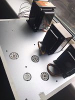
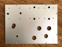
build is coming along slowly, here are some photos:
Attachments
Last edited:
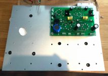
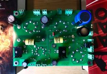
board is done. mounted it on the top plate.
Attachments
-
 200640438_155630716601976_3918373425316943395_n.jpg245.8 KB · Views: 67
 -
 197774392_3250767575150517_6882934725841306499_n.jpg397.9 KB · Views: 68
 -
 195764984_823428488570080_6179433980627902906_n.jpg274.3 KB · Views: 110
 -
 197774389_388542442568082_1871964756487055942_n.jpg357.4 KB · Views: 109
 -
 199678829_318623923232942_8792155928303965128_n.jpg124.1 KB · Views: 60
another question guys, the OPTs have 4/8/16 ohms taps, my speakers are 8 ohms nominal with minimum dip at just below 6ohms. should I use the 8 or 4ohms tap?
thanks.
Looking through the thread I did not see mention of the output tubes, the operating point and details about the output transformers (primary impedance). That might help in getting a more intelligent reply.
Without that, IMHO, your speakers present a very benign load and should do well on the 8 Ohm taps, unless your transformers reflect a low primary load for the output tubes you plan to use.
Nice work. Good luck.
- Home
- More Vendors...
- Tubelab
- need assistance on SSE build