To all:
Looks like Mouser has discontinued their 47 uF, 500V rated electrolytic caps needed for C1, unless you buy 475 of them. Mouser is my source (without going into the why's of my choice, it needs to be Mouser).
The datasheet for the 5AR4 lists allowable values of the first capacitor (Cap Input Filter) as 4 to 60 uF. So, in theory C1 could be any standard value from 4 to 60 uF. 500V or better rating is needed, clearly for the SimpleSE.
However, can anyone convince me whether I should upsize/downsize to the next standard values, being 33 uF of 56 uF.
Neither seems to have much impact on the final B+ voltage (PSUDII sims), but the 56 uF seems to create a little more start up voltage overshoot than the 33 uF.
Danke
I would not go up in value. The larger the C1, the more stress it puts on the 5AR4 during the power-on surge. New production tubes are more prone to arching over. I would go with 33uF.
I recommend going smaller as well. Most power transformers don't have enough winding resistance to make a 5ar4 happy. That 60uF figure usually requires extra 150ohm plate resistors to increase the impedance of the power supply enough to prevent arcing over. 47uF is already too much for some modern 5ar4 versions. 
See rating chart 3 in the GE 5ar4 data sheet.
http://www.drtube.com/datasheets/5ar4-ge1959.pdf
See rating chart 3 in the GE 5ar4 data sheet.
http://www.drtube.com/datasheets/5ar4-ge1959.pdf
I would not go up in value. The larger the C1, the more stress it puts on the 5AR4 during the power-on surge. New production tubes are more prone to arching over. I would go with 33uF.
I recommend going smaller as well. Most power transformers don't have enough winding resistance to make a 5ar4 happy. That 60uF figure usually requires extra 150ohm plate resistors to increase the impedance of the power supply enough to prevent arcing over. 47uF is already too much for some modern 5ar4 versions.
See rating chart 3 in the GE 5ar4 data sheet.
http://www.drtube.com/datasheets/5ar4-ge1959.pdf
Thanks guys.
Any other thoughts on the stock values in the other section of the PS CLC filter (i.e. the selection of PS Choke 5H/10H and C2/C.aux) that follow?
My current BOM selections are a 5H (ESR 58R) Edcor unit (cost driven), with a 120uF electrolytic for C2 and an ASC 40uF/440VAC motor run cap for Caux.
Those selections are probably fine. 5H is a little low, especially given the low 58 ohm DCR (I assume that's that you meant). Some additional series resistance might be warranted to get closer to the 150 ohms of the original design. Folks typically run a bigger motor run cap (70-100uF range), but it's not that critical. I went with a 220uF C2, since I had it on hand and it fit the PCB.
Adding SS diodes, can help 5AR4/GZ34 life too without hurting sonics.
See post #18 and discussion:
Does the type of 5AR4 influence the sound? - Page 2 - AudioKarma.org Home Audio Stereo Discussion Forums
Randy
See post #18 and discussion:
Does the type of 5AR4 influence the sound? - Page 2 - AudioKarma.org Home Audio Stereo Discussion Forums
Randy
Attachments
Adding SS diodes, can help 5AR4/GZ34 life too without hurting sonics.
See post #18 and discussion:
Does the type of 5AR4 influence the sound? - Page 2 - AudioKarma.org Home Audio Stereo Discussion Forums
Randy
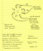
Not sure this would work with the printed circuit board mounted octal socket. Pins 5 and 7 go to nowhere and you'd have to jumper pins 2 and 8 to allow the socket to be rotated to make it work according to your sketch.
I believe that since the diodes are in series with the HV windings, they could be added to the bare winding leads and the diodes inserted into the terminal strip at the board edge in the design.
While I must be hallucinating, I seem to remember a thread somewhere on DIYAudio that mentioned this. Can't find it now.
Since I'm a novice at the tube stuff (OK with soldering), I am leaning toward an essentially stock build. This thread started based of the preferred value for C1 being unavailable at a preferred supplier AND limitations on my budget due to a limited WAF. Currently what the amp will eventually look like leads to uncertain WAF. If I spend too much, the WAF will tend toward zero.
😀
There is another thread somewhere about wiring in diodes
Yes, that would work to just put them in series from the PS leads to the circuit board , paying attention to polarity. You could use heat shrink tubing to make it safe and sturdy.
That drawing is for point to point wiring saving using a terminal strip as there are convenient unused pins handy.
Anyway it will help the tubes last for years for a few cents as UF4007 diodes are at the most 35 cents each.
Randy
That drawing is for point to point wiring saving using a terminal strip as there are convenient unused pins handy.
Anyway it will help the tubes last for years for a few cents as UF4007 diodes are at the most 35 cents each.
Randy
Last edited:
The subject has come up for amps like the Dynaco ST-70, which push the 5AR4 more than some other designs do. The modern tubes don't like it.
Dropping C1 to 33uF would normally have a negligible effect on ripple. The relatively low DCR and inductance of your choke makes me suggest that you make up for it anyway with a bit more C in C2. It's probably not going to matter, but it's something to think about.
Dropping C1 to 33uF would normally have a negligible effect on ripple. The relatively low DCR and inductance of your choke makes me suggest that you make up for it anyway with a bit more C in C2. It's probably not going to matter, but it's something to think about.
Squiffy, your choices look fine...and as Russ mentioned, the low DCR of your choke may result in a bit higher B+ than anticipated. You can always swap in a 5U4; that usually drops about +/- 30V than a 5AR4, depending on current draw. The 5U4 comes to life a lot faster than a 5AR4, so you lose some of the benefits of a soft start. Well, you still get a soft start but you'll get some B+ overshoot since the 5U4 will be conducting before the output tubes are warmed up.
If the first cap value stays above about 10uf or so in a CLC PS, it won't change your final B+. Reducing the value of the first cap to less than 8-10uf or so will start to reduce your B+ voltage as the first cap value gets smaller. So you can always try some 1uf - 5uf or so caps for C1 to bring down your B+ if req'd.
Model your PS in PSUDII and play with the choke DCR and the value of the first cap for a quick and easy demo/sim.
...it will help the tubes last for years for a few cents as UF4007 diodes are at the most 35 cents each.
Is doing this in concert with a thermistor (GE CL90) in the 120VAC mains and a thermistor (GE CL140) on the HV secondary centre tap do anything for/against adding the UF4007 diodes to the HV secondary leads? I can't think of anything untoward they might do in concert. But, would having the thermistors heat and bring up voltage slowly hurt the diodes in any way?
Dropping C1 to 33uF would normally have a negligible effect on ripple. The relatively low DCR and inductance of your choke makes me suggest that you make up for it anyway with a bit more C in C2. It's probably not going to matter, but it's something to think about.
The C2 value doesn't have much impact on cost. The Caux value affects both sourcing where I live about 40 miles west of Toronto and cost. The 40 uF unit is readily available at a reasonable $20. Once I start calling HVAC contractors to but a motor run cap, the extortion starts along with upselling service on my furnace and central air. Sheesh.
Squiffy, your choices look fine...and as Russ mentioned, the low DCR of your choke may result in a bit higher B+ than anticipated.
What I am seeing in PSUDII is an overshoot in B+ in the first few milliseconds up to about 500V, then undershooting from the final B+ of about 435V by a few volts, in my case (360-0-360 HV). Ripple is minimal.
You can always swap in a 5U4; that usually drops about +/- 30V than a 5AR4, depending on current draw. The 5U4 comes to life a lot faster than a 5AR4, so you lose some of the benefits of a soft start. Well, you still get a soft start but you'll get some B+ overshoot since the 5U4 will be conducting before the output tubes are warmed up.
Would the thermistors mentioned above have any impact on using a 5U4 and slowing its effects down a little?
I think I am more inclined to follow earlier advice and place some additional resistance in series with the choke to get the DCR closer to the 150R value of the design's R1 that is replaced by L1.
If the first cap value stays above about 10uf or so in a CLC PS, it won't change your final B+. Reducing the value of the first cap to less than 8-10uf or so will start to reduce your B+ voltage as the first cap value gets smaller. So you can always try some 1uf - 5uf or so caps for C1 to bring down your B+ if req'd.
Model your PS in PSUDII and play with the choke DCR and the value of the first cap for a quick and easy demo/sim.
The Amperex Datasheet I have for the 5AR4 shows the first cap should not be any lower than 4uF, which I tried. The B+ voltage did drop quite a bit. Little variation for C1 at 22, 30, 33, 47 and 56 uF.
I am trying not to stray too far afield from the suggested parts list, while trying to work in some budget limits for wife acceptance factor. I'd also considered Ty Bower's suggestion of switching to an LCLC ladder filter instead of the original Pi filter. Cutting a trace in the PCB is not in my plans right now.
I had also considered asking Edcor about the price impact of a custom winding on their XPWR002-120 power Tfmr by adding additional taps so I could get a 250-0-250 or 300-0-300 for other tube types like the older 6L6 family, for example. Then, swap the HV wires from the normal 360-0-360 to the lower ones and presto, lower resultant B+.
A guy can dream, can't he?
Appreciate the feedback from all.
Would the thermistors mentioned above have any impact on using a 5U4 and slowing its effects down a little?
I had also considered asking Edcor about the price impact of a custom winding on their XPWR002-120 power Tfmr by adding additional taps so I could get a 250-0-250 or 300-0-300 for other tube types like the older 6L6 family, for example. Then, swap the HV wires from the normal 360-0-360 to the lower ones and presto, lower resultant B+.
A guy can dream, can't he?
Appreciate the feedback from all.
The CL60/140 warm up pretty fast (like a second or two) at rated current, and will have little impact on the difference in warm up between a 5AR4 and a 5U4.
The Edcor NRE fee for a custom transformer is $40. Once someone orders one and pays the extra fee, it becomes stock product, like the XPWR-131 that Russ (Rknize) had made for the Tubelab SE so that we all can enjoy it. Thanks again Russ! It's a little shy on max secondary voltage for an SSE (330-260-0-260-330) though.
Not sure this would work with the printed circuit board mounted octal socket.
The diode trick does seem to help save 5AR4's especially some of the new "stuff". To do this on an SSE simply solder a diode on the end of each red transformer lead, put heat shrink over it and screw the free end of the diode into the terminal block.
Is doing this in concert with a thermistor (GE CL90) in the 120VAC mains and a thermistor (GE CL140) on the HV secondary centre tap do anything for/against adding the UF4007 diodes to the HV secondary leads? I can't think of anything untoward they might do in concert. But, would having the thermistors heat and bring up voltage slowly hurt the diodes in any way?
No problem here. I have an SSE running with the diodes, and a CL-140. It works just fine. The diodes are being added to the next revision of the PC board. I must remove the old screened on name. The CL-140 might go in too, it depends if I can fit the parts without ripping too much up and changing things. That would require a whole bunch of new testing. Either way, it won't be ready for a month or two. You can put the CL-140 on the red/yellow transformer lead too.
A 33uF C1 cap is fine, and I too have seen the same issue with 47uF caps. I don't know what is going on with 500 volt caps, but the supply is sporadic and the prices are all over the place. Right now a 47 uF costs more than a 100 or 120 uF IF you can find them.
The 40 uF unit is readily available at a reasonable $20.
The 40 uF is good too. The purpose of the motor run cap is to provide a low ESR through the upper audio frequencies where some electrolytics start to behave like inductors. Their guts are wound up into coils of foil, paper and goo, so they ARE inductors. The electrolytic does the hard work, the motor run fills in the details. My TSE uses a 20 uF because that's all that fits in the chassis.
The CL60/140 warm up pretty fast (like a second or two) at rated current
There are two possible places to install an inrush current limiter. Either, or both can be done in the same amp.
The usual place is in series with the transformer primary. I have done this. It serves to slow down the surge that comes when you flip the power switch, which can prevent switch arcs, and save tube heaters. It does little to help the rectifier tube since it warms up faster than the tube does. Use a CL-70, 80 or 90 here based on the size of the amp. An SSE gets a CL-90 since it tends to draw just over 1 amp.
You can put a CL-140 in series with the center tap of the HV secondary. It adds 50 ohms at turn on and drops to about 5 or 10 ohms after the rectifier tube is conducting. The CL-90 isn't good here since it needs a minimum of .5 amps. The current here is NOT even close to a sine wave and can't be measured with a meter. Even the CL-140 doesn't fully warm up, but it does help save rectifier tubes.
have anyone tried the 274A rectifier without changing the cap value ?
I have the stock value capacitor (47uf / 500V), the 193j hammond choke and a 80uf motor run cap ...
I have the stock value capacitor (47uf / 500V), the 193j hammond choke and a 80uf motor run cap ...
This may be too late for the OP, but I just ordered a 47 uF 500V JJ brand cap from partsconnexion, it's about $6. I haven't heard much about them, but one member here said they are the best sounding electrolytics he's ever tried. They are designed for tube amp PS duties so I think they should be a good choice. Size is 22mm diameter x 42mm height, so it should fit on the PCB.
https://www.partsconnexion.com/capacitor_ele_jjcap.html
https://www.partsconnexion.com/capacitor_ele_jjcap.html
Parts Connexion is about 30 minutes from my house and they let me do pick ups after completing my orders. Great to know this...hadn't considered them for passive components beyond sockets, pots and coupling caps.This may be too late for the OP, but I just ordered a 47 uF 500V JJ brand cap from partsconnexion, it's about $6. I haven't heard much about them, but one member here said they are the best sounding electrolytics he's ever tried. They are designed for tube amp PS duties so I think they should be a good choice. Size is 22mm diameter x 42mm height, so it should fit on the PCB.
https://www.partsconnexion.com/capacitor_ele_jjcap.html
Got the JJ 47 uF 500V cap in and it fits the PCB just fine, it is 2x the size and 3x the weight of the original cap I was using... I also got 200 uF caps for my preamp project and they are also large and heavy for electrolytic caps.
I believe those caps are using older electrolytic designs, which is why they are bulkier. This is on purpose, as they are more for replacements in vintage equipment. In the C1 position it will work just fine. I have used them before in new amps without issue.
The diode trick does seem to help save 5AR4's especially some of the new "stuff". To do this on an SSE simply solder a diode on the end of each red transformer lead, put heat shrink over it and screw the free end of the diode into the terminal block.
Which way do the diodes go?
- Status
- Not open for further replies.
- Home
- More Vendors...
- Tubelab
- SimpleSE: C1 value