Anyone tried these in the Tubelab single ended?
A big lot of ex FAA tubes was given to me a few months ago. In going through the lot I see some 801A's. Aside from the 7.5 volt filament, these look like they should drop right in to the TSE, and should easily outperform 2A3 ( which isn't saying much, 5930's are all I really care for in this family ) and be as good or better than 300B, and 307A / VT-225.
The thoriated tungsten filament should look good in the amp. My Tubelab SE has been down for rebuild for quite a few months now, really ever since I veered off on the 6146 tangent, and I'm thinking when I put it back together I might try these tubes in it.
Win W5JAG
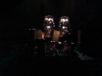
Well, those pictures sucked. Maybe these will be larger.
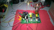
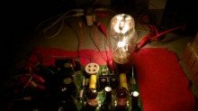
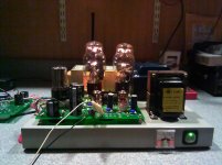
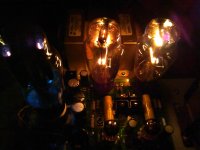
The first picture is with the room lights on. I made a few changes ( and blew up a part after that pic was taken ). The second is with the lights out; all the light seen is coming from that single 801A - you can see the 801 actually casting shadows.
I can see, I think, how this is going to go: Step 1 was getting past the 7.5 volt filament hurdle.
Step 2: shifting the range of bias voltage to make it more suitable for the 801.
Step 3: These tubes are going to need B+ voltage beyond what a normal TubelabSE would see. The upper end of the typical 300B B+ voltages is probably going to be about the minimum that 801 wants to work at.
When I first powered it up, it was running around 200 volts on the plate - I was using the same small PT that I used to bring the board back to life after it's long hibernation, and make sure everything was working as it should. I had a 45 on the board for that.
With a 7K load, the 801 didn't sound good at 200 volts. At 300 volts, about as much as I can wring from that little PT, and after listening for awhile, I found myself really liking it. I think I liked it better than the 45, although, in fairness, I kept the 45 down around 200 volts. From looking at the data sheets, I'm not pulling as much current as I expected at a given bias point, so I'm not yet sure what is up with that.
Win W5JAG
Attachments
First, the disclaimer:
The TSE was not intended for operation with 801 tubes. Anytime a product is made to do something other than the intention of its designer, bad results are possible. A one off modification may, or may not, be repeatable. Some choices and experimentation will be required. Some choices and experiments may lead to bad results including, but not limited to, component damage. Anyone embarking on modification of their TSE board must be aware of, and accept the possibility of, such bad results.
In other words, just don't do it.
The TSE board was designed for operation with 45/2A3/300B tubes using directly heated oxide coated cathodes at up to 6.3 volts.
The 10/50/801 family of tubes uses directly heated thoriated tungsten cathodes at 7.5 volts. The thoriated tungsten operates at a much higher temperature and glows with a brilliant white light, much like a small electric light bulb.
The regulator on the TSE board is specified for a maximum voltage output of 5 volts. It MAY be possible to use this regulator as part of the conversion process by elevating the chip a few volts above ground so that it only sees 5 volts across it, when the output voltage is actually higher. I didn't try this. I decided the simplest solution was to remove the regulator from the board, together with one lead of R2. This allows easy access to the cathodes of the power tubes.
AC versus DC
The AC versus DC decision is a choice that must be made to proceed with the conversion. Some audiophiles say AC sounds better on the cathodes of DHT tubes, and that this is especially true for thoriated tungsten tubes. There is a resistance in the cathode, so with DC applied, there will be a temperature difference from one end of the cathode to the other that would not exist if AC was used. There is a big potential for, maybe a certainty of, low level 60 and 120 Hz IMD products in the amplified output when using AC.
I went with DC for several reasons: First, the designer is a practicing engineer and I'm not. Second, the RCA 801 data sheet curves are all specified at DC on the cathode. Third, the use of DC allows the existing filament/cathode supply to be used as designed, largely intact. Fourth, there are no provisions on the TSE board for hum reduction components if AC were to be selected; it was not readily apparent to me that there is a convenient way of installing them.
In short, DC seems likely to produce the best result, and presents the fewest practical problems in the process.
The Voltage Situation
The data sheet specifies 7.5 volts so that would seem to be that. It does not specify a tolerance. In doing some casual internet reading on this, most of the ( anecdotal ) information on this subject is from experience with, or in some instances actual manufacturer data, on the thoriated tungsten filaments of bigger RF power tubes. It goes something like this: the tolerance is typically specified on these tubes as + - 5 per cent. Operation above this tolerance is really bad and will lead to shortened tube life, and operation below this tolerance is really bad and will lead to shortened tube life, except that there is an undervoltage condition, of 3 or 4 per cent less than nominal, where tube life is greatly extended. The anecdotal evidence of this with big transmitting tubes comes from both broadcast and amateur operations, and is common enough that I accept it as true. I have no idea if any of this applies to small RF tubes like 801, or, if it even does, whether AC or DC was being used on the cathode. I suspect AC.
There is also the "starved triode" school of thought that suggests that with small and large ish DHT's, performance improves dramatically at reduced cathode voltages, as evidenced by actual measured data reported here by Steve Bench:
DHT with starved filaments.
Further, Steve Bench postulates that there is a relationship between power drawn by the cathode, and permissible current drawn by the plate, and that cathode undervoltage need not, and will not, lead to shortened tube life, so long as plate current is reduced in some proportion to the reduction in cathode power:
Heater / Filament Efficiencies
His site looks to be long extinct, but is mirrored on several other sites, and there looks to be no follow up to support or refute this proposition.
To proceed, I removed the 2.5 volt jumpers previously installed on the board, and put the 6.3 volt transformer jumpers in place on the board. I soldered a jumper across the pads on the back of the board that would normally be used for input and output of the regulator chip.
In theory, a 6.3 volt AC output should rectify out to well over 8 volts. In practice, once the outout is loaded down, it's a lot less. My power transformer is significantly oversized for a project like this, so it is very lightly loaded by the current requirements of the 801A's and 5842's.
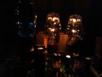
With both 801A's in place, I measure about 7.3 volts DC on the cathodes at initial turn on, which drifts down to about 7.1 volts over time. It appears that as the 801A's warm up, the cathodes draw more current until they stabilize at operating temperature and current. This is a smidgen below the lower tolerance limit for 801A, but probably within the margin limits of my measurement devices. I measured 6.0 volts on the 5842 filaments.
I doubt that in practice, this will cause any real difficulty. The color looks normal.
In theory, a 6.3 volt AC output should rectify out to well over 8 volts. In practice, once the outout is loaded down, it's a lot less. My power transformer is significantly oversized for a project like this, so it is very lightly loaded by the current requirements of the 801A's and 5842's.
With both 801A's in place, I measure about 7.3 volts DC on the cathodes at initial turn on, which drifts down to about 7.1 volts over time. It appears that as the 801A's warm up, the cathodes draw more current until they stabilize at operating temperature and current. This is a smidgen below the lower tolerance limit for 801A, but probably within the margin limits of my measurement devices. I measured 6.0 volts on the 5842 filaments.
I doubt that in practice, this will cause any real difficulty. The color looks normal.
Attachments
The Bias Supply
When I was first testing the 801's at lower plate voltages than they are intended to operate at, I was concerned that the TSE bias supply would need some rework, as I couldn't move the bias voltage positive enough to get the current draw I was seeking. I think there are a couple of reasons for this: one, the plate voltage was too low. Two, the cathode voltage was low enough ( 6.7 volts ) that, combined with the low plate voltage, it just needed less bias than the board could nominally supply.
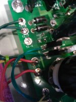
My TSE board was originally built for 45's. My power transformer has a separate screen voltage winding that produces dc output voltages in the mid - low 250's when used with a circuit similar to that of the bias supply on the TSE. To avoid the inconvenience of changing out the dropping resistors on the TSE board, it seemed logical to use the screen voltage taps. The bias rectifiers are nominally fed by the HV secondaries on a stock TSE board. To access these rectifiers independently, the easiest and most convenient way is to simply lift one leg of each diode from the board, and solder the lower voltage secondary directly to the leads of the diodes.
I measured the range of bias voltage at each socket as being approximately -30 to -80 volts. Once the 801A's were being fed with proper plate voltage ( I have begun at 380 volts ) this range is adequate to properly bias 801A.
When I was first testing the 801's at lower plate voltages than they are intended to operate at, I was concerned that the TSE bias supply would need some rework, as I couldn't move the bias voltage positive enough to get the current draw I was seeking. I think there are a couple of reasons for this: one, the plate voltage was too low. Two, the cathode voltage was low enough ( 6.7 volts ) that, combined with the low plate voltage, it just needed less bias than the board could nominally supply.
My TSE board was originally built for 45's. My power transformer has a separate screen voltage winding that produces dc output voltages in the mid - low 250's when used with a circuit similar to that of the bias supply on the TSE. To avoid the inconvenience of changing out the dropping resistors on the TSE board, it seemed logical to use the screen voltage taps. The bias rectifiers are nominally fed by the HV secondaries on a stock TSE board. To access these rectifiers independently, the easiest and most convenient way is to simply lift one leg of each diode from the board, and solder the lower voltage secondary directly to the leads of the diodes.
I measured the range of bias voltage at each socket as being approximately -30 to -80 volts. Once the 801A's were being fed with proper plate voltage ( I have begun at 380 volts ) this range is adequate to properly bias 801A.
Attachments
The 801A needs high ish voltage for a small ish tube, and it also needs a high plate load impedance, 10K or greater.
The only chassis I had readily available that could meet these requirements was the venerable SSE board that has seen countless hours of use and misuse. As an additional bonus, it had the lower voltage secondary available for the bias supply.
Indeed, I think this chassis has the capability for SV 811 or SV 572, although these bottles may be too big to fit the spacing on the TSE board.
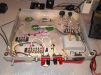
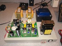
Anyway, the SSE board, screen supply, and unnecessary bits were removed from the old chassis, and on went the TSE board. A 47 uf 450 volt cap was installed as the first cap in the B+ supply, and some other bits I had blown up were replaced before the board was installed.
If it looks like it got wired in a linear fashion, that's because it did. Although I had already re verified he board to be in proper working order ( less the blown bits ), I proceeded one step at a time in an abundance of caution, testing as I went. It took about three hours from beginning dismantlement to listening to the 801 TSE on the new chassis.
First, I wired in the Hammond 125ESE OPT's and set the load for 10K.
Next I wired up the 7.5 volt and 5 volt secondaries, and individually tested each for proper operation before proceeding.
Next the bias secondary was wired up, and range of voltage at each socket was measured. Bias was set to maximum negative prior to installation of the power tubes.
Finally, the high voltage secondary was wired in, and B+ was confirmed to exist at the power tube sockets. For initial power up and testing, I chose a 5W4GT rectifier. It can easily handle the current requirements of 2 5842's and 2 801A's.
The only chassis I had readily available that could meet these requirements was the venerable SSE board that has seen countless hours of use and misuse. As an additional bonus, it had the lower voltage secondary available for the bias supply.
Indeed, I think this chassis has the capability for SV 811 or SV 572, although these bottles may be too big to fit the spacing on the TSE board.
Anyway, the SSE board, screen supply, and unnecessary bits were removed from the old chassis, and on went the TSE board. A 47 uf 450 volt cap was installed as the first cap in the B+ supply, and some other bits I had blown up were replaced before the board was installed.
If it looks like it got wired in a linear fashion, that's because it did. Although I had already re verified he board to be in proper working order ( less the blown bits ), I proceeded one step at a time in an abundance of caution, testing as I went. It took about three hours from beginning dismantlement to listening to the 801 TSE on the new chassis.
First, I wired in the Hammond 125ESE OPT's and set the load for 10K.
Next I wired up the 7.5 volt and 5 volt secondaries, and individually tested each for proper operation before proceeding.
Next the bias secondary was wired up, and range of voltage at each socket was measured. Bias was set to maximum negative prior to installation of the power tubes.
Finally, the high voltage secondary was wired in, and B+ was confirmed to exist at the power tube sockets. For initial power up and testing, I chose a 5W4GT rectifier. It can easily handle the current requirements of 2 5842's and 2 801A's.
Attachments
Initial power up was uneventful, thankfully. The bias had already been set to maximum negative on each power tube.
I installed the 5842's and verified they were drawing current on the panel meter. I connected a speaker to the right channel, installed the right power tube, and adjusted the bias for an additional 40 ma on the meter. Thoriated tungsten tubes are "instant on" devices. I jumpered an audio source to the right inputs, and verified that music in produced music out at the test speaker.
I placed a 10 ohm dummy load across the left speaker and installed the left power tube. I adjusted the bias on the left channel for another 40 mils on the panel meter.
I then removed power, cooled everything down, and swapped the speaker and dummy load to verify that music in produced music out at the test speaker on the left channel.
Then, I took a few more measurements and just listened. Until 1:00 AM. With the 5W4, B+ at the power tube pins is 380. Bias is, IIRC, -40 ish. Cathode voltage is noted above. Eventually, I will work it up to about 440 volts, the limit of my filter caps.
The inputs remain to be wired to the board. I am undecided on metering. These are trivialities.
I have read the 801A sounds thin. That is definitely not true as installed in the TSE. Even on my crappy test speaker, the 801 TSE has the robust dynamics of a 6L6 and the detail of a 45. I only expect it to get better as more voltage and current is applied.
Win W5JAG
Attachments
I got to play with it a bit late last night.
480 volts on the anode is about as high as I can go, without exceeding the plate dissipation. By using a solid state rectifier, I could maybe eke out another 10 volts, but I don't have enough bias adjustment to keep the currrent as low as I would like it. My filter caps are rated at 450 volts, so this is a smoke event waiting to happen as it is.
Anode 480 volts
Current 36 mils
Grid Bias - 32 ( I was tired and forgot to measure grid current )
Cathode 7.2 volts ( measured with a better device, I think, than previously )
17 watts. The nominal rating is 20.
This is spot on with the plate curves on the data sheet.
With a cathode voltage of 7.2, I'm at the point where I am in the anecdotal extended tube life part of the tolerance range ( if there is such a thing ), or I am in the safe current area for a starved triode condition as per Bench, and am putting his theory to the test, sort of, since there is no control tube.
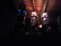
Subjectively, it sounds big and robust. After not having heard them for several years, I had forgotten how linear DHT's sound. My radio room is smallish, 8 x 12, the speakers are some small Yamaha's, not too efficient at 86 dB (IIRC), and I have to sit close to them. Despite these limitations, it sounds good, maybe as good as those Yamaha's have sounded. It sounds more dynamic than I expected, but retains that triode clarity, for lack of a better phrase. I wonder if this is a result of the higher voltages this tube sees. I think I understand why people get bitten by the bug to build kilovolt class triode amps.
It's back in it's place on the shelf in the shack, while I weigh possible metering options.
Win W5JAG
480 volts on the anode is about as high as I can go, without exceeding the plate dissipation. By using a solid state rectifier, I could maybe eke out another 10 volts, but I don't have enough bias adjustment to keep the currrent as low as I would like it. My filter caps are rated at 450 volts, so this is a smoke event waiting to happen as it is.
Anode 480 volts
Current 36 mils
Grid Bias - 32 ( I was tired and forgot to measure grid current )
Cathode 7.2 volts ( measured with a better device, I think, than previously )
17 watts. The nominal rating is 20.
This is spot on with the plate curves on the data sheet.
With a cathode voltage of 7.2, I'm at the point where I am in the anecdotal extended tube life part of the tolerance range ( if there is such a thing ), or I am in the safe current area for a starved triode condition as per Bench, and am putting his theory to the test, sort of, since there is no control tube.
Subjectively, it sounds big and robust. After not having heard them for several years, I had forgotten how linear DHT's sound. My radio room is smallish, 8 x 12, the speakers are some small Yamaha's, not too efficient at 86 dB (IIRC), and I have to sit close to them. Despite these limitations, it sounds good, maybe as good as those Yamaha's have sounded. It sounds more dynamic than I expected, but retains that triode clarity, for lack of a better phrase. I wonder if this is a result of the higher voltages this tube sees. I think I understand why people get bitten by the bug to build kilovolt class triode amps.
It's back in it's place on the shelf in the shack, while I weigh possible metering options.
Win W5JAG
Attachments
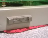
This is an coulometric (sp?) elapsed time indicator, 1968 Curtis Instruments vintage. These were probably expensive devices in their day, but I got 4 for a dollar when I bought them.
I was afraid they might not be good, but the indicator was about a day under zero, and, after applying power for a day, it was right at starting point zero. The data sheet indicates an accuracy of +- 3% over the range 100-130VAC.
These measure out to one thousand hours, and, unlike many of these devices, the data sheet describes a simple reset procedure, making it reusable for many measurement cycles.
Unfortunately, this amp being in my radio room, it may take a long time to accumulate one thousand hours.
Still undecided on other parameters to be metered.
Win W5JAG
Attachments
Grid current
Grid current.
Should I be seeing any? Only in A2?
If so, how much?
Can I measure for it across the 100 ohm grid resistor?
The tubes are running 450 volts, 37 mils.
Win W5JAG
Grid current.
Should I be seeing any? Only in A2?
If so, how much?
Can I measure for it across the 100 ohm grid resistor?
The tubes are running 450 volts, 37 mils.
Win W5JAG
Should I be seeing any? Only in A2?
I don't know much about the 801A, so I can't say how much grid current there will be if any. The grid will draw current only when it is pushed above the filament by the audio signal (grid more positive than the cathode / filament). On a 45 this will be less than 5 mA. I have seen 300+ ma on an 833A.
I made the measurements with a dual trace scope. Put one probe one each side of the 100 ohm resistor and set up the scope to display the difference between the channels. On my 20 year old TEK2232, I set the ADD/ALT/CHOP switch to ADD, then press the invert button on channel 2. You should see nothing until the amp is driven hard enough to push G1 positive WRT the filament, then there will be current only on positive going signal peaks.
A digital meter will only display random garbage, but an old analog fast movement may bounce like a VU meter if there is enough grid current.
Brief experiments with an 811A years ago proved that they draw grid current most of the time.
Thanks, George.
I did try it with a DMM, and did get meaningless garbage.
I tried again with my portable digital scope, but only used one channel across the 100 ohm resistor, and was just looking at the drive signal. I wasn't seeing a bg voltage across it - couple of volts p-p, at a pretty good speaker volume, so it may not get pushed hard enough to draw grid current.
In looking at my handheld scope, I can add channels, but don't see an invert function. Read the manual time, I guess. My bench scope is only single trace.
I had it oscillating into slow runaway last night - seemed to be related to the input cable I was using. The 5842's - both of them - were oscillating. I watched the 801's go all the way to 25 watts, never saw any color in them.
Win W5JAG
Last edited:
Scope the grid (WRT ground) and see if it is indeed being driven positive. Some tubes, especially old DHT's don't respond too well to A2. They are emission limited. If most (or all) of the electrons leaving the filament are making it to the plate, driving the grid positive will only steal some of these electrons resulting in a REDUCTION in plate current.
When I started down this SE road about 14 years ago I was throwing minimum bids at every cheap 45 that showed up on Ebay. I wound up with fifteen or twenty 45 tubes for less than $10 each. Many were called "weak" or "well used" but most all of them worked fine in a TSE. I run them at 325 volts and 30 mA. If you dig up the old RCA specs for the 45 they show an AB2 push pull operating condition spec that results in 18 watts from a pair. I have an old Australian spec that shows a pair making 19 watts while drawing a "peak grid current" of about 8 mA. Many of my old 45 tubes worked fine in the TSE, but only a few could produce 15 to 20 watts without excessive distortion due to lack of emission capability.
When I started down this SE road about 14 years ago I was throwing minimum bids at every cheap 45 that showed up on Ebay. I wound up with fifteen or twenty 45 tubes for less than $10 each. Many were called "weak" or "well used" but most all of them worked fine in a TSE. I run them at 325 volts and 30 mA. If you dig up the old RCA specs for the 45 they show an AB2 push pull operating condition spec that results in 18 watts from a pair. I have an old Australian spec that shows a pair making 19 watts while drawing a "peak grid current" of about 8 mA. Many of my old 45 tubes worked fine in the TSE, but only a few could produce 15 to 20 watts without excessive distortion due to lack of emission capability.
Attachments
Scope the grid (WRT ground) and see if it is indeed being driven positive..
I'll try this the next time I'm out there.
This set of 801A's is all I have right now. I'm sure they were well used, but test really strong on my TV-7/D. I haven't looked for these types at local hamfests to see how available they are.
I'm seeing lots of 10's and 10Y's on ebay - at shocking prices. I don't care much for 2A3's - I've thought about putting a note down in the buy / sell forum to see if anybody wants to swap 2A3's for 801's. Keeping my 5930's though.
I have one pair of SV-811's, mu 10 type, and I expect these will now pretty well drop in and work just fine, maybe a slight filament voltage adjustment at most. I don't know that my onboard tranny can do eight amps - I might have to parallel in another transformer to feed a pair of these. More B+ might be better, but I think they will work at 450 - 475.
Win W5JAG
OK, I put the scope on the grid, referenced to ground. Reading DC, with 801A, it swung plus or minus 50 volts around the static bias setting of -52 volts.
On AC, the p-p voltage was about 80 volts.
BTW, I can state that SV811-10 rock out on this board, and in this configuration. Even pulling NINE amps - voltage on the 811 cathodes held steady at 5.9 right up to the point .... it didn't .....
So now I have PS issues to troubleshoot. It still works, sort of, but sags uselessly under a nine amp strain, struggles at 5 amps, and is down about a volt even with the miniscule drain of the 801's. I'm seeing 5 volts on the 5842's, so it looks to me like the two diodes in the lower half of the filament supply are probably resistors. Better diodes than laminations, though.
Anyway, the 811-10's do rock the house. Looking at the data sheet, I shouldn't be able to bias them, but in practice, I could. With 460 volts on the plate, I could bias them all the way to the limit of my OPT's. I set them at 70 mils, 460 volts, loafing along at 32 watts shaking the damn walls out here when the PS let go. Still had the plate load at 10K, although the few designs you see out there are running at 5K.
The above grid voltages are with the 5842's only seeing five volts on the heaters.
Diodes have been the bane of my existence this year 😡.
Win W5JAG
- Status
- Not open for further replies.
- Home
- More Vendors...
- Tubelab
- 801A in Tubelab Single Ended?