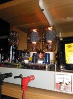
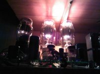
But, on a positive note, here are the SV-811 cranking away.
This also shows the metering I settled on: I replaced the ammeter with a voltmeter reading the voltage on the 7.5 volt line; and added a couple of banana jacks on the front panel - the switch toggles between the two channels for reading plate current on the power tubes, and also lets me read the B+.
I whacked some HF probes in half to make the right angle connectors.
The volt meter has already come in handy, darn it.
Win W5JAG
Attachments
Well, it's repaired, and back in 801 service.
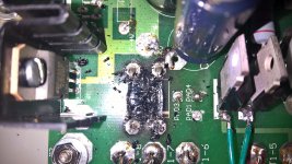
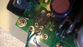
I've had the parts for awhile, but put off the repair, in part because of the tedious nature of work in that part of the TSE board, and in part because the need for rework was entirely a function of stupidity, which I really didn't need a reminder of.
Anyway, as I expected, the damage below board was a lot worse than the damage above board. The traces were pretty well toasted, more resistance than conductor I expect, in light of the increasing voltage drop with increasing current. Since I had it apart, I replaced both 1N5401 and the schottkey dual diode, although I expect all the aberrant behavior was due to burnt 1N5401's and traces. I also replaced the 6.3 volt capacitor in the filament line of the 801A's with a 10,000 uf 10V part, and replaced the power supply electrolytics with 500 volt parts.
It's working nominally, 6 volts on the 5842 heaters, and a steady 7.2 on the 801's under load. It hasn't taken me long to make this board look as trashed as the SSE board I pulled from this chassis. 🙁
I have to say, the 811's are the real deal, and having the opportunity to have tried them out was worth the mayhem it caused. They will get more attention in the future.
Win W5JAG
Attachments
Not sure how I missed all of this before - but awesome stuff! I was thinking the same thing, as I have a spare board and some SV811's lying around. I was going to go completely off board for the heaters though: cut the traces and use coleman supplies.
Well, my board actually ran for about six hours over the course of several days with the SV811-10's before I smoked it, and I can say with complete confidence that, with the single exception of the 6.3 volt heater supply to the power tubes, the TSE board is ideal for this tube. It worked so well, I wouldn't even consider scratch building a circuit for this tube - I don't see how the TSE design can be improved on.
With a B+ of 450 volts or better, the 811-10 biases easily with no adjustments to the bias circuit required, the powerdrive can drive it easily to wall shaking volume with no adjustments required, and it seems to be unconditionally stable, even at only 5.9 volts on the cathodes. The bias curent held rock steady on both channels ( better than the 801A's) and there was no trace of oscillations. I expect SV-572-10 would be easily driven by the powerdrive as well, but more B+ is probably necessary.
The only glitch is the best way of getting the nine amps needed for the two sets of filaments into the board. I will definitely revisit this tube on this board at some point in the future - it's too good a combination not to.
I think that the best way would be to bypass the traces completely and to bring the high current dc directly to the pins of the 811's, and let the rest of the onboard filament circuitry, sans the regulator, handle the 417A's. I doubt that a fancy fiament supply is necessary. I expected some hum with the higher filament voltages, but it turned out better than I thought it would - zip on 86 dB speakers, and a little up close to the speakers on 96 dB Klipsch's. Ths is with no special precautions taken to avoid hum, a basic dc supply with 10,000 uf as the only filtering, so it can probably be worked out with a little time and attention.
Keep us in the loop if you go there!
Win W5JAG
Had it on the bench last night to play with it some. With 801A's, at low voltage - 425 volts at 40 milliamps:
Tested with a range of single tone, sine wave, frequencies between 1 KHz and 6 KHz inclusive, output clipping was observed at 2.1 volts RMS input. I measured a consistent 1.6 watts output into a 9 ohm resistive load, when flattening of the sine wave output was observed on a scope.
I measured distortion at 3% IMD at 1 watt output. I have less confidence in the distortion measurement, both in technique and accuracy of equipment.
Clearly, It's not getting to A2. When I get a chance, I'll repeat at higher voltages to see what, if any, difference that makes.
It sounds more robust than 1.6 watts, but, that's what I measured. Maybe it takes a big clip before you really hear it.
Win W5JAG
Last edited:
Another tough night in the TSE 801 world. Playing with it on the bench at 490 volts, I let the smoke out of ( at least ) the right side CCS.
Yes, a 5842 can be made to glow as bright as one of Tubelab's 6BQ6 "tests". 😱
However, I do think I got it into A2 - before the fire, I was seeing 6+ watts on each side without any flat topping of the sine wave.
Progress, I guess.
I'm seeing 492 volts on the plate of the 5842, so, I guess the 10M45 has gone kerblamo. A 5842 looks like a nuclear meltdown at that voltage ......
Last edited:
A 5842 looks like a nuclear meltdown at that voltage ......
I melted one in exactly the same manner. They are only rated for 450 volts. I think mine blew right around 500, and like most sand based life forms, they fail to a dead short. The 10M90 is rated for 900 volts.
I'll replace both with the 10M90's when I do another parts order. Thanks for that tip.
I think the 10M45 on that side has been flaky since day one. I've had persistent, intermittent, oscillation problems on that side, on two different chassis, so, good riddance to it.
The final tally for the evening is ( at least ) one shorted 10M45, one smoked 330 ohm resistor, two likely ruined 5842's, a shorted commie rectifier, and a pile of fuses ( not sure how I smoked the rectifier, didn't expect that - and went through almost my entire stock of 1.5 amp fuses before figuring that one out - and not a Radio Shack within ninety miles at present ).
Still, I consider it a good night on the bench. It was bugging me that I was only getting 1.6 watts at 40 mils and 425 volts. Looking at the data sheet, I should have been able to get that at 425 volts and only 18 mils. So, I went back and set everything up according to the data sheet: B+ 425 volts, -40 on the grids, this gave a little more than 19 milliamps plate current, and I did measure the same 1.6 watts, but at about twice the IMD. I'm not sure about the absolute magnitude of my measurements, but I feel fairly confident with the trend - less is less, even if I'm not sure of the exact number. Is that to be expected - more current equals less distortion, similar to the SSE models?
And, I saw a lot more output when I got it up to close to 500 volts. I set the static values almost right at the data sheet point for 500 volts. I got 6 + watts on each side without flattening of the sine wave - more than double the data sheet value - at about the same distortion as 1.6 watts. At the same time, plate current almost doubled, so I am assuming it did go into class A2? As soon as I killed the drive, it went back to the data sheet static values.
So, not all bad. And, I found a set of silver plated 4CX250 sockets, with the built in bypass caps, when I was frantically searching for more low amp fuses. I thought I had gotten rid of all that type of stuff when I decided another kw amp was way down on the project list.
Win W5JAG
Hmmm ..... 850 mils on the right power tube ..... 264 volts on the grid ..... a 2SK3563 didn't want to be left out of the party ....
Left side sounds great though, so I have a nice monobloc until I get around to getting replacement parts .....
Win W5JAG
Left side sounds great though, so I have a nice monobloc until I get around to getting replacement parts .....
Win W5JAG
OK, I've got a head scratcher going on here.
It's going to take me a while to exhaust enough inventory to justify placing a parts order; as a stop gap, I just pulled the board, and replaced the 10M45 and 2SK3563 with new parts I had in stock.
And this is where it all goes south.
I now have B- everywhere. And, I mean everywhere. It's on the grid of the power tube, where it should be. It's on the plate of the power tube, where it shouldn't be. And it's on the plate of the 5842 where it definitely should not be. And, this is on both channels - the left channel *was* working properly, before I repaired the right.
I only see a couple of paths for B- to the 5842. The first would be a shorted coupling capacitor. To eliminate this, I lifted a leg of each coupling cap. This had no effect.
The next path is through the B+ rail, if all of the silicon gets shorted ( half of this is new, and half worked just fine a few hours earlier). But, the silicon does not seem shorted. Logically, if I have B- on the power tube grid and 5842 plate, and the coupling cap is gone, shouldn't I have a very low resistance path from the power tube grid to the plate of either 5842? But, I don't - it's almost infinite.
Ohmmeter measurements don't suggest either 2SK3563 is shorted. But neither is working properly, either - I can only swing the bias from about - 199 to - 185 on both channels.
And there is now a B+ problem. As in, there is no B+. The only way to get rid of the B- is to remove ac power from the FRED's. But there is no B+, at any of the tubes. I have B+ out of the rectifier. I have B+ on both ends of the choke. I have B+ at the + pin of the last filter cap. But, nothing at the 10M45, and nothing at the power tubes.
Probably something simple, but right now its got me stumped.
Win W5JAG
Most likely the through hole plating at the drain of U2 (10M45) is open. Measure continuity from the + end of C5 to the junction of R29 and R18. B+ gets there through the hole for U2.
Good call.
Touched it up on both CCS, and B+ is back at all plates.
CCS on both sides looks to be operating properly. No positive voltage on the power tube grids.
Grid voltage looks right - adjusts normally in the expcted range on both sides.
Wow, that saved a lot of troubleshooting. Thanks !!!!
Win W5JAG
Touched it up on both CCS, and B+ is back at all plates.
CCS on both sides looks to be operating properly. No positive voltage on the power tube grids.
Grid voltage looks right - adjusts normally in the expcted range on both sides.
Wow, that saved a lot of troubleshooting. Thanks !!!!
Win W5JAG
And it was, indeed, that center pin on U2 - the CCS I replaced. On visual inspection, the solder did not wick through to the top side of the board.
I touched up all the other pins on both just for good measure ......
Win W5JAG
I touched up all the other pins on both just for good measure ......
Win W5JAG
I think my initial thoughts on using the 801A were wrong, and the defining characteristic of successful employment of the 801 on the TSE board is current through the tube, and not voltage across it.
The magic number seems to be 50 milliamps, plus or minus only a few milliamps. As the plate rating is twenty watts, by definition this limits voltage to 400 volts or so.
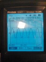
The first pic below is the output of a 1 kc sine wave into the TSE 801, 25 milliamps current at 425 volts, being delivered into an 8 ohm resistive load. 10 volts p-p into 8 ohms is 1.6 watts, if my arithmetic is correct. In fact, this is the data sheet output value for an 801A at this operating point - it will do this at 20 milliamps. This is also the data sheet point for a type 10 at these same points, if one cares to look. This is all 801 will do, until you get to markedly higher current through the tube.
The 10 may have less distortion at these numbers - I can't say because I don't have any. I'll put them on my hamfest look list to see if I can get some examples.
Now, ( second pic ) look at the same 1 kc sine wave into the TSE 801, 50 milliamps current at 410 volts, being delivered into an 8 ohm resistive load. 20 volts p-p into 8 ohms is 6 + watts, if my arithmetic is correct. And, IMD is markedly better at higher current - at all output levels, you can literally watch IMD drop as current is increased in the tube. Above 50 mils, the decline in IMD is slight and insignificant; not worth pushing the tubes past their rating in my opinion.
I repeated these tests at higher voltage ( up tp 450 - I didn't want to set anything on fire like the last excursion to 500, and it now seems unnecessary to go there ) and lower currents to get the same twenty watts power through the tube, and consistently ran up against the 1.6 watt limit before the sine wave showed distortion. Thus my conclusion: current important, voltage - as long as it's above 400 or so, not so important. And, the number for current is 50 milliamps.
The third pic is a 10 kc square wave at about 3.5 watts output. I don't know much about interpreting square waves - I'll leave that to someone else. The ringing looks to be on the low side of the wave. The sine wave also distorts asymetrically, beginning on the low side of the wave. This is consistent on both my analog scope and the digital one.
Sorry the pics are not better - these are on my handheld digital scope to use the hold feature, and for my convenience on the bench - it's an older scope so the resolution is lacking compared to newer models.
All of these were with the Hammond 125ESE at 10K load.
I think I'm about done here until I can get some 10's or 50's. I've looked briefly at lower plate loads, but distortion seems to go up significantly at 5K, so I don't see much point in looking at that further.
Hopefully, this information will be useful to someone. This was an easy conversion and easily reversible, and if one has 801' s laying around the results seem to have been worth the minimal effort.
Win W5JAG
The magic number seems to be 50 milliamps, plus or minus only a few milliamps. As the plate rating is twenty watts, by definition this limits voltage to 400 volts or so.
The first pic below is the output of a 1 kc sine wave into the TSE 801, 25 milliamps current at 425 volts, being delivered into an 8 ohm resistive load. 10 volts p-p into 8 ohms is 1.6 watts, if my arithmetic is correct. In fact, this is the data sheet output value for an 801A at this operating point - it will do this at 20 milliamps. This is also the data sheet point for a type 10 at these same points, if one cares to look. This is all 801 will do, until you get to markedly higher current through the tube.
The 10 may have less distortion at these numbers - I can't say because I don't have any. I'll put them on my hamfest look list to see if I can get some examples.
Now, ( second pic ) look at the same 1 kc sine wave into the TSE 801, 50 milliamps current at 410 volts, being delivered into an 8 ohm resistive load. 20 volts p-p into 8 ohms is 6 + watts, if my arithmetic is correct. And, IMD is markedly better at higher current - at all output levels, you can literally watch IMD drop as current is increased in the tube. Above 50 mils, the decline in IMD is slight and insignificant; not worth pushing the tubes past their rating in my opinion.
I repeated these tests at higher voltage ( up tp 450 - I didn't want to set anything on fire like the last excursion to 500, and it now seems unnecessary to go there ) and lower currents to get the same twenty watts power through the tube, and consistently ran up against the 1.6 watt limit before the sine wave showed distortion. Thus my conclusion: current important, voltage - as long as it's above 400 or so, not so important. And, the number for current is 50 milliamps.
The third pic is a 10 kc square wave at about 3.5 watts output. I don't know much about interpreting square waves - I'll leave that to someone else. The ringing looks to be on the low side of the wave. The sine wave also distorts asymetrically, beginning on the low side of the wave. This is consistent on both my analog scope and the digital one.
Sorry the pics are not better - these are on my handheld digital scope to use the hold feature, and for my convenience on the bench - it's an older scope so the resolution is lacking compared to newer models.
All of these were with the Hammond 125ESE at 10K load.
I think I'm about done here until I can get some 10's or 50's. I've looked briefly at lower plate loads, but distortion seems to go up significantly at 5K, so I don't see much point in looking at that further.
Hopefully, this information will be useful to someone. This was an easy conversion and easily reversible, and if one has 801' s laying around the results seem to have been worth the minimal effort.
Win W5JAG
Attachments


Last edited:
Here are a few measurements of 801 TSE.
These were made with a newly built Heathkit AA-1 Audio Analyzer. This was not my first choice of instrument; however, I've not hamfested much in the last four years for better hardware, so I decided in January that I might as well build it and use it. It's been pretty useful - I'm wondering now why I didn't build it years ago.
My tubes now have 100 hours on them according to the elapsed time meter. The test as 74 and 74, from an original reading of 80 each. The TV-7/D is not all that precise or repeatable a measurement, so while they look to have lost some transconductance, it's hard to say how much.
My 417A's seem to suck. They measure weak as a 5842 on the TV-7/D settings, and good ( barely ) using the earlier TV-7/B settings. I have them set at the recommended value of 170 volts for these tests, although that is not the optimum point for them. An aditional 0.2-0.3% improvement can be obtained by adjusting them for optimum.
Here are the results, thus far:
B+ Ik %IMD at: 2W 1W 500mW 100mW
435 19 68 52 30 4
428 25 58 35 16 3.6
425 30 48 20 8.5 2.9
423 35 40 11 6.2 2.3
420 40 30 7.2 4.8 1.8
415 45 25 5 3.2 1.5
413 50 14 4.2 2.8 1.25
The IMD test is hard, I think, for a single ended amplifier, but the 801 TSE acquits itself well.
Epilogue
It's pretty easy to see that the 801A makes a pretty lousy 10. I would hope 10's do better at their operating point, but I have none, so can't say.
It's also easy to see how increasing the standing current in the 801's dramatically reduces the IMD measured by this device. For casual listening such as talk radio, etc., the lower current points are actually fine; for music I usually move them up to at least 35 ma.
One of the interesting things is being able to watch the power output on the meter in real time, without having to do all the arithmetic from a p-p scope display. I have Yamaha's in my radio room, that, IIRC, are 86dB, 89dB, somewhere in that range, sensitive. In other words, not very sensitive. But, I also find that, allowing for ballistic lag of the analog meter, 40-50 mW produces a comfortable volume level and excursions past 200 mW are non existent. I can run it at around 500mW average and after about 20 minutes, my ears are ringing from the sound pressure in that small room.
Since it can be driven into A2, it has ample power reserve. I haven't measured the distortion there - I have to hook up to two external generators to do that. I have them, but just haven't done it yet.
It's unclear yet whether the reduced filament voltage is having any effect on tube life.
I have found some distortion difference between 801 left and 801 right, 801 left being somewhat higher above the 2 watt level at high(er) currents.
Is this due to the reduced filament voltage? I tested 801 left at 7.5 volts, and while not exactly a perfect analog as B+ was about three per cent higher, it did indeed match, within about 0.1 %, the distortion readings for 801 right when the filament voltage was increased. I then retested 801 right at 7.5 volts and found marginally higher distortion readings for it at 7.5 volts.
So, go figure. It would take a lot of tubes to make any conclusions about the merits of lower filament voltage versus distortion, I think. Right now, given the limited quantities of these things left, it's probably pure luck.
Some commenters suggest that higher loads are better for these tubes. I have used mine at 10K and the numbers above are at 10K. I tried to trick the Hammonds into reflecting a 20K load, and saw markedly worse numbers. Either I was unsuccessful, or 20K is a bad choice. I plan on getting some more OPT's so I can free up my 125ESE for other projects. I will order 10K transformers.
For anyone contemplating an 801 build, I would go with 10K. I would not go with less than 10K. The 125ESE looks to me to be a reasonable choice for the 801A.
That's all I know for now. Hopefully this limited information will be useful to someone.
Win W5JAG
Just for curiousity, I thought I would check the frequency response of the Hammond 125ESE I am using as OPT's on this amp.
The conditions were plate set for 10K, secondary 8 ohm, the load was 8 ohm resistive, current through the OPT is 50 mils at 415 volts.
I set 1 Khz as the 0 dB point at 1 watt output. 100 Hz was -1db, 70 Hz was - 2 dB, and 55 Hz was - 3dB. The high frequency response was flat to 6 kHz, where it began a very gentle roll off out past 30 kHz. 10 kHz was down about -0.5 dB, 15 kHz was about -0.8 db, 20 kHz was -1.5 dB and 30 kHz was - 2 dB.
IIRC, the specification is 100 Hz to 15kHz + - 1 dB, so after eight years of hard use, sometimes abuse, thousands and thousands of hours, they still meet specification per my mediocre test equipment.
The interesting thing is this - when I was running the tests, I noticed that I had failed to put a load on the unused channel. I started to install a resistor to load it it down, and while I had one lead of the resistor attached to the hot banana jack, and the other end floating, I took a pretty good bite across the finger that was touching the hot lead of the resistor.
It sure felt like RF.
Once I had the load resistor in place, I got out my handy Dick Smith Electronics ( anyone here in the states remember them? ) "grid" ( it's solid state ) dip meter, and probed the output up to about 300 MHz, and couldn't find anything. Touching the resistor leads once it's in place is a non event.
I can still feel the point where it went in my finger, and well up into my arm, so I'm pretty sure it was RF. The amp seems stable, sounds quite good, measures quite good for an SE amp, so, don't know. It was just unexpected.
Win W5JAG
Last edited:
- Status
- Not open for further replies.
- Home
- More Vendors...
- Tubelab
- 801A in Tubelab Single Ended?