Sheldon said:
With those figures, I get about 360V.
Sheldon
Sheldon: I'm curious why our B+ results of Luvdunhill's model inputs are so far off. (440V vs 360V)
I'm assuming that your model differs from the one I've attached....
Attachments
boywonder said:
Sheldon: I'm curious why our B+ results of Luvdunhill's model inputs are so far off. (440V vs 360V)
I'm assuming that your model differs from the one I've attached....
that's exactly what I get as well. I probably just communicated something incorrectly in my post ..
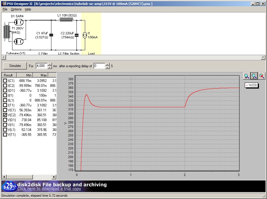
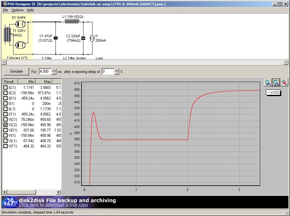
Here are my simulations, if that helps you at all. The stepped load shows two things: full load stability for the first two seconds. The last two seconds shows the load with only the bleed resistor...i.e. the maximum voltage the filter caps will see.
"45 mode"
"300B mode"
I have also attached the PSUD files, if that will be useful.
"45 mode"
"300B mode"
I have also attached the PSUD files, if that will be useful.
Attachments
boywonder said:
Sheldon: I'm curious why our B+ results of Luvdunhill's model inputs are so far off. (440V vs 360V)
I'm assuming that your model differs from the one I've attached....
luvdunhill said:
that's exactly what I get as well. I probably just communicated something incorrectly in my post ..
No, I did a quick sim the first time and didn't check it out. The discrepancy is due to a minor bug in the program.
The default value for a current source is 100mA. I entered 40mA, and that value shows up on the schematic. But, sometimes, my program goes to stepped load, even if I don't check the box or enter any other values. When that happens, the program steps to 100mA (or whatever previous value was entered) at 0 seconds. In other words, the current is 100mA but the schematic shows 40mA. Can't tell, unless you open the current source edit box.
Run with 40mA, I get what you display for your sims, so yours are the correct values.
Sheldon
rknize said:The stepped load shows two things: full load stability for the first two seconds. The last two seconds shows the load with only the bleed resistor...i.e. the maximum voltage the filter caps will see.
That overshoot you see will not actually occur in practice. For the tube rectifier, you can go to the options menu and click on "soft start". That will more accurately reflect the gradual warm up of the rectifier filament. Not a big deal one way or the other, in your case, as your bleed resistor has no warm up cycle.
Sheldon
Yeah, I don't care about the overshoot because it doesn't happen in practice. What is important is the stability. Leaving soft start off will show if the filter is damped enough or not. This is also where a stepped load can be revealing as you will definitely see ringing.
rknize said:Yeah, I don't care about the overshoot because it doesn't happen in practice. What is important is the stability. Leaving soft start off will show if the filter is damped enough or not. This is also where a stepped load can be revealing as you will definitely see ringing.
Yes, on that score you are good - well damped. I've seen some people claim that a power supply that is a touch underdamped sounds better. A matter of taste, I guess. Also probably depends on the amp itself.
Sheldon
rknize said:I have also attached the PSUD files, if that will be useful.
Thanks, Russ! I'll play with them. I guess your resistance values are all based on actual measurements?
PaulyT said:Thanks, Russ! I'll play with them. I guess your resistance values are all based on actual measurements?
They are closer now. I used these models when I came up with the specs for that transformer. The only thing I did was update the secondary's DCR and re-run it. The result is pretty close to what I measured on the amp.
The resistance values in the caps are the spec'ed ESRs from Panasonic, not anything I measured. Note that C2 is 220uF because that is the cap I am using. It does not account for the film cap I will be adding to the final amp. The breadboard testing was done with a 220uF electrolytic cap...no film cap. The lower net ESR on C2 from the film cap is not going to have any significant impact on the simulation. The only thing you would probably notice is slightly higher current leaving the choke when the rectifier switches off.
If you are not familiar with electronics, graphing the voltages and currents through the various components of a filter like this is a real crash course in how capacitors and inductors behave. Kind of interesting.
I'll take some better DCR measurements of the transformer and then post the actual secondary voltages, both unloaded and loaded, back in the other thread for reference.
Sheldon said:
I've seen some people claim that a power supply that is a touch underdamped sounds better. A matter of taste, I guess. Also probably depends on the amp itself.
Sheldon
Assuming that underdamped supplies have lower resistance, could the lower output resistance contribute to better sound? I'm still confused about the design goals: should you shoot for a highly overdamped supply or a critically damped supply?
If critically damped is the design goal, it seems that utilizing a transformer with more volts than you need and adding RC/LC sections to get the desired reduction in B+ also yields great ripple reduction, but at the expense of increased output resistance.
boywonder said:Assuming that underdamped supplies have lower resistance, could the lower output resistance contribute to better sound? I'm still confused about the design goals: should you shoot for a highly overdamped supply or a critically damped supply?
Darn good question. From an engineering standpoint, you'd want the stiffest supply possible within budget constraints. But maybe in some amps, an underdamped supply sounds more musical - at least to some people, than a highly damped supply. Why? Your guess would be as good as mine.
boywonder said:If critically damped is the design goal, it seems that utilizing a transformer with more volts than you need and adding RC/LC sections to get the desired reduction in B+ also yields great ripple reduction, but at the expense of increased output resistance.
This is where PSUD is your friend. Play with endless combinations. No solder no parts cost.
Sheldon
My EE is pretty rusty having done software for well over a decade, but I do remember that to critically damp a LC filter, you want sqrt(L/C)/R = 0.5. The R includes the resistance of the choke, the rectifier and the transformer secondary. For a C(R)LC filter, some Thevenin analysis is needed and I'm not sure how to do a straight-up calculation of that.
I cheat and poke at it with PSUD until it doesn't ring anymore and does what I want. 😛
I cheat and poke at it with PSUD until it doesn't ring anymore and does what I want. 😛
That's a valid equation, in agreement with Morgan Jones V.A. p. 322. I don't believe the Rdc of the transformer comes into play, however, unless you are dealing with a strictly choke input supply. And in that case, I would suspect the L of the transformer would also play a role.
In PSUD experiments (which very closely mimic actual circuit response), I have found this damping to be a little difficult to achieve unless you add quite a bit of resistance in series with the choke, but getting close to damping of 0.5 produces good transient response and a pretty good power supply to my ears.
In PSUD experiments (which very closely mimic actual circuit response), I have found this damping to be a little difficult to achieve unless you add quite a bit of resistance in series with the choke, but getting close to damping of 0.5 produces good transient response and a pretty good power supply to my ears.
Oh yeah...I was going to mention that. In practice, you need a lot of C to get a choke filter not to ring. When looking at practical circuits, especially old ones where C was very expensive, you rarely see this. Instead the goal seemed to be to dampen the circuit enough so that it doesn't ring at audible frequencies and then isolate the higher gain stages with additional RC networks. So it seems the B+ rail on the output plates would flop around at subsonic frequencies. Not the best solution, but it worked.
As for the resistance of the secondary...no that would not com into play in the latter half of a CLC filter. What you really have though is a RCRLC filter where the rectifier and transformer are accounted for in that first R.
Anyway...just splitting hairs....
As for the resistance of the secondary...no that would not com into play in the latter half of a CLC filter. What you really have though is a RCRLC filter where the rectifier and transformer are accounted for in that first R.
Anyway...just splitting hairs....
- Status
- Not open for further replies.
- Home
- More Vendors...
- Tubelab
- PSUD newbie: modeling Tubelab SE