A solid state amplifier would have no trouble driving 16 ohms. In fact, this would be a very safe load - no danger of the amplifier blowing up like when there is too low an impedance.
The power transferred to the speaker load is likely to be smaller, but not so much as to be audibly noticeable.
Thank you! This was the assurance I was seeking.
") jj
jjYou guys got me thinking about phase and polarity. I looked up this site, and it offers the best and clearest explanation I could find. Remember; I'm looking for clear and simple solutions.
Phase vs Polarity explained | JustMastering.com
jj
Phase vs Polarity explained | JustMastering.com
jj
@ GUNFU and benb
You are both correct, so please bin my offending statements!
Phase or polarity. It depends on whether you are technical or not, it seems to me. I know only one is correct, but it is rather like bulb or lamp (in the UK). To an electrician the round glowy thing is a lamp. To the consumer it is a bulb, and a lamp is the thing it is fitted to.
The hifi consumer is more likely to understand phase than polarity in this context.
Thanks, jimmyjoe. The mathematical explanation is particularly helpful and I've simplified it slightly for future reference as follows:I looked up this site, and it offers the best and clearest explanation I could find. Phase vs Polarity explained | JustMastering.com
Phase is just another name for delay as a proportion of wavelength. If we delay a pure 200Hz sine wave by 180°, we delay it by 2.5ms.
But now imagine that instead of a pure sine wave we have a complex waveform at 200Hz with a couple harmonics, at 400Hz and 600Hz.
When we delay the complex waveform by 180°, i.e. 2.5ms, we are changing the phase of its individual components differently. The 200Hz part is delayed by 180°, as we would expect; but the 400Hz component is delayed by 360°, not 180°; and the 600Hz component is delayed by 540°, which is 180° + 360°.
In contrast, when we reverse the polarity of a complex waveform, the phase of every single frequency component is changed by 180°.
Delay should also be able to be defined over a region. When it is it can be said that a fixed delay will not provide a fixed phase shift with frequency, and vice versa.Phase is just another name for delay as a proportion of wavelength.
I read the article jimmyjoe mentioned, and I don't understand this last part, the mathematical analysis.
"So from a mathematical point of view, this is the difference between changing the phase and polarity of a complex waveform (A) relative to another (B) within a mix:
When you reverse the polarity of complex waveform A, you change the phase of all its frequency elements equally, by 180°. This changes the phases of the individual frequencies in waveform A relative to B in the mix. For example, if the relative phases in A and B of the 200Hz and 400Hz elements were 170° and 10° respectively, the new relative phase of the 200Hz element will be 180° + 170° = 350°, and the new relative phase of the 400Hz element will be 180°+10° = 190°. As a result, the 200Hz element in the mix will get much louder, and the 400Hz element will get much softer.
When you delay complex waveform A relative to B, you change the phase of each of its frequency elements by a different amount. This again changes the relative phases of the individual frequencies in the mix, but in a different way. If we take the example above but delay waveform A by enough to shift the 200Hz element by 180° instead of changing polarity, the new relative phase of the 200Hz element will again be 180° + 170° = 350°, but the new relative phase of the 400Hz element will be 360° + 10° = 370°. As a result, the 200Hz element in the mix will again get louder, but the 400Hz element will keep the same volume."
Not having much in the way of maths, I would have thought that every frequency would have nulled or doubled. Can someone explain it in words of less than one syllable?
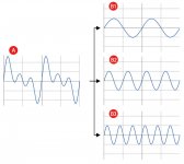
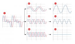
I'll give it a try! Consider when complex waveform A and complex waveform B each contain the same sine wave component.
A zero degree phase relationship between the two sine wave components would make them perfectly in phase, giving the highest combined signal level.
A 180 degree phase relationship puts them perfectly out of phase, resulting in total phase cancellation - and therefore silence as the combined output.
All the other possible phase relationships put the two sine wave components partially out of phase with each other, resulting in partial phase cancellation.
It is this phase cancellation between the constituent sine wave components to which the mathematics in jimmyjoe's article is referring - sometimes louder, sometimes softer and sometimes the same.
The attached diagrams are courtesy of Sound On Sound (SOS) magazine. Read the full article here: Phase Demystified
Attachments
But the article I quoted refers to a 180 deg polarity switch changing the relative levels of different frequencies. That's what I don't understand. If that is so, how does the null test work?
Ah wait! I missed that it was adding to another wave of the same frequency but with a different phase angle. That makes more sense, as he is talking about mixing.
As you were.
Ah wait! I missed that it was adding to another wave of the same frequency but with a different phase angle. That makes more sense, as he is talking about mixing.
As you were.
Last edited:
I don't know whether I should say this or not, but I'll take a chance:
I have no problem with words.
I have no problem with charts.
I have no problem with animations.
I have severe problems with mathematics. Don't know why; it's just a total mental block.
Due to the kindness and patience of the people in this thread, I've learned more about things I didn't understand in the last few weeks than I learned in my whole life. I can't thank you guys enough. jj
I'm not an expert in mixing so you prompted me to check out what you mean by the null test - courtesy of the SOS article....how does the null test work?
If you want to check whether two audio files are exactly identical or not. Just line up the two files so that their waveforms are exactly in phase with each other, and then invert the polarity of one. If they're identical, you should get total phase-cancellation (in other words, complete silence) when combining them.
I'd just like to return to this as Jim did refer to medium priced solid state amplifiers.Why at 8 ohms? For solid-state, the lower the load resistance, the higher the power until it fails or the protection starts to work.
I have, in my collection, a Rogers Ravensbrook Series III which was an affordable amplifier of the early 70s and is still sought after today. It was rated by the manufacturer at 20W into 8ohm.
Last night, I unearthed the Hi-Fi News magazine test results on a vintage Ravensbrook III that were carried out in 2016. Interestingly, the power output was measured as follows:
No figures for 16ohm are given, but I think it is safe to say that the maximum power is developed into 8ohm with this particular amplifier.Power Output (<1% THD): 22W/8ohm; 19W/4ohm
Dynamic Power (<1-2% THD): 28W/8ohm; 19W/4ohm; 16W/2ohm; 8W/1ohm
I wonder how a modern budget solid state amplifier (not one of those audiophile behemoths!) would fair under similar test conditions?
I thought I was finished, but I have another question.
There are many amplifiers that operate in what is called "Class A". It's been said that some are and most aren't ..... true class A, that is.
Here's what I've been told:
Class A devices pull constant power from the outlet. With no signal, a class A amp is simply producing heat. Signal sent to the speaker is simply less of that constant pull that is converted to heat. Whether the amp is driving a 4 ohm, 8 ohm or 16 ohm speaker makes no difference; the power drawn from the wall outlet is the same.
If that is true, wouldn't a simple amp meter around the power cord as several different signals are introduced to the amp tell the whole story?
Again .... thank you for your help. jj
There are very experienced amplifier designers on this forum, but here is my humble contribution which an expert may care to correct or expand upon.
In Class A, the output device (transistor or valve) is constantly carrying current, causing a continuous loss of power in the amplifier and generating heat.
The large amount of heat generated results in a class A amp having very low efficiency in converting DC supply power to RMS power in the loudspeaker - let's say around 30%
To produce 3W of RMS output power in the loudspeaker would therefore require 10W to be supplied by the DC power supply - the missing 7W generates heat in the amplifier.
To produce 6W in the loudspeaker would require 20W to be supplied by the power supply - the missing 14W generates heat.
So, the input power requirement increases as the output power increases and a wattmeter on the input cord would show that.
However, such disproportionate loss of power as heat requires a really beefy and expensive power supply, That's why Class A amplification is limited to low power applications.
I must say, people here are teaching me a good lesson regarding my poor ability to communicate clearly!
Let's try again.
A man told me that most amplifiers that are advertised as class "A" are actually not. In class "A", the amp has a constant pull from the wall (as measured by an amp meter) regardless of signal level or speaker impedance. This means that for all levels of output lower than clipping, the ampere draw of the amplifier will not change. If it does, the amplifier is NOT class "A".
True or not?
Thank you for your help. jj
We both need an expert to chime in, Jim! 
However, this is what I now read!
"In a true class A amplifier, the power that is dissipated as heat in the output device at idle is passed on to the load at full power. The average current is the same as the idle value, so there is no change in the current from the supply."
Technical Q&A
However, this is what I now read!
"In a true class A amplifier, the power that is dissipated as heat in the output device at idle is passed on to the load at full power. The average current is the same as the idle value, so there is no change in the current from the supply."
Technical Q&A
Annoyingly, I have just returned a Class A GM70 SE amp to the manufacturer, otherwise I could have measured the current draw!
Ouch! bad timing!
We both need an expert to chime in, Jim!
However, this is what I now read!
"In a true class A amplifier, the power that is dissipated as heat in the output device at idle is passed on to the load at full power. The average current is the same as the idle value, so there is no change in the current from the supply."
Technical Q&A
Hmmmmmm. Seems to support what I heard. Thank you! jj
However, such disproportionate loss of power as heat requires a really beefy and expensive power supply, That's why Class A amplification is limited to low power applications.
I have listened to a 120 watt class A amp, and its 100 kg or so. So yes PSU and heatsink gets massive. The amp was Dali Gravity.
- Status
- This old topic is closed. If you want to reopen this topic, contact a moderator using the "Report Post" button.
- Home
- Member Areas
- The Lounge
- different audio forum