I decided to look this up, interesting. I thought the silica laden compound in the middle was to allow the tyre to warm up even when the road was cold. Come to think of it they seem harder than they should for the grip they have.And I am more familiar with hysteresis in tyres, particularly motorbike tyres.
Another question:
This site Amplifiers states that there is possible phase shift to amplifiers. Can anyone characterize whether this is common to audio amplifiers, especially moderately priced audio amplifiers? And if it does exist as a common occurrence, how bad is it? Is it audible?
Thanks. jj
This site Amplifiers states that there is possible phase shift to amplifiers. Can anyone characterize whether this is common to audio amplifiers, especially moderately priced audio amplifiers? And if it does exist as a common occurrence, how bad is it? Is it audible?
Thanks. jj
Man, I have GOT TO remember to make myself clearer! That wasn't the kind of phase shift I was thinking of. I was thinking (if I read the site correctly) of a circuit that has phase shift that varies with frequency. For arbitrary example, a phase lag of maybe 10 degrees at 100 cycles, and a phase lag of triple that at 1,000 cycles.
You can tell that I can't find specific examples on the 'net ..... probably because I don't know how to search accurately. Hope I made the question a little clearer this time. jj
You can tell that I can't find specific examples on the 'net ..... probably because I don't know how to search accurately. Hope I made the question a little clearer this time. jj
Phase shift is also associated with amplifier components such as capacitors. Phase Shift
Let's look at the case of a capacitor in series with a resistor. At frequencies where the reactance of the capacitor is small compared with the resistance the shift in phase is low and may be ignored, but at frequencies where the reactance of the capacitor is high the phase shift is high also. If the reactance is twice the resistance the phase shift is of the order of 60°.
'Stray' capacitances and inductances in the circuit also introduce phase shifts.
To create a stable amplifier, such phase shifts must be controlled - that is the skill of the amplifier designer!
Amplifier ParametersThe design of multi stage amplifiers must take phase shift into consideration, as the amount of phase shift will vary with frequency it is possible that at some frequencies the total phase shift may add up to 360 degrees. If the output signal of such a system is allowed to re-enter the input then positive feedback occurs and the amplifier will become unstable and is likely to oscillate.
" ...To create a stable amplifier, such phase shifts must be controlled - that is the skill of the amplifier designer! ..."
Aha! I think you've given me the answer ..... again! I didn't know whether or not such phase shifts were inevitable in certain designs. It seems that they are NOT inevitable ... given a skillful designer.
It's funny how so many things in this life, in so many different circles of endeavor, are critically dependent upon the skill and insight of certain individuals and NOT upon blind adherence to formulae and dogma.
Thank you. jj
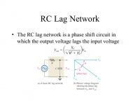
To elaborate further on a series RC circuit, the phase shift will vary with frequency from 90° to 0° when the frequency changes from nearly zero to infinity.
This is because the RC circuit behaves capacitively at low frequencies and resistively at high frequencies.
Such phase shifts are inevitable, but their effects are mitigated by careful amplifier design,
This is because the RC circuit behaves capacitively at low frequencies and resistively at high frequencies.
Such phase shifts are inevitable, but their effects are mitigated by careful amplifier design,
Attachments
Man, I have GOT TO remember to make myself clearer! That wasn't the kind of phase shift I was thinking of. I was thinking (if I read the site correctly) of a circuit that has phase shift that varies with frequency. For arbitrary example, a phase lag of maybe 10 degrees at 100 cycles, and a phase lag of triple that at 1,000 cycles.
You can tell that I can't find specific examples on the 'net ..... probably because I don't know how to search accurately. Hope I made the question a little clearer this time. jj
Yes, there is phase shift in all amplifiers, and poles associated with it. What is relevant to amplifier stability is the slope of the high frequency rolloff. At some frequency it changes from 6 dB/octave to 12 dB/octave. This is what you have to look at when designing a global feedback amplifier.
Look up Nyquist stability criteria and Bode plots. Walt Jung talks a lot about it. Also our own member Tom has an article about applying Nyquist stability criteria to the LM3886 chip amp. He's done extensive research on the LM3886 and offers some of the best products that use it.
I looked up Nyquist (or Nyquist-Strecker) and I can assure you of one thing beyond any shadow of a doubt: that stuff is beyond me.
Look up Bode plots. They illustrate stability vs loop gain with a graph. You can look up the open loop gain vs frequency plot of a chip amp (like the 3886) and draw your Bode plot right on that. It will tell you what you need to know, without using a bunch of math. Here's a simple explanation (note the section on "Rules for handmade Bode plot"
)Bode plot - Wikipedia . Then you superimpose your closed loop gain on the Bode plot (typically a straight horizontal line with) and you note where it intersects the Bode plot. If the slope is 6 dB/octave, then you have enough phase margin. If the slope is 12 dB/octave, then you don't have enough phase margin and the amplifier will be unstable. At 6 dB/octave, your phase margin is 90 degrees. At 12 dB/octave, your phase margin is 180 degrees- in other words, out of phase. Your negative feedback has become positive feedback. You want the 12 dB/octave part of the curve to be well away from your closed loop gain plot.I do all this with a cheap engineering calculator and graph paper. It takes practice and familiarity with phase response. After doing a few it becomes pretty predictable. I wish I had a tutorial to link to. Walt Jung has an excellent explanation in one of his books. I know somebody here could explain it better than me.
I looked up Nyquist (or Nyquist-Strecker) and I can assure you of one thing beyond any shadow of a doubt: that stuff is beyond me.
Look at figure 49 in the datasheet LM3886TF/NOPB Texas Instruments | Mouser This is essentially a Bode plot, courtesy of the manufacturer. You can measure it and plot it too, no fancy pants math needed. You can superimpose your closed loop gain on this graph and see where it intersects the plot.
A solid state amplifier would have no trouble driving 16 ohms. In fact, this would be a very safe load - no danger of the amplifier blowing up like when there is too low an impedance.
The power transferred to the speaker load is likely to be smaller, but not so much as to be audibly noticeable.
The power transferred to the speaker load is likely to be smaller, but not so much as to be audibly noticeable.
Here people are usually afraid of chairs.Yes, no need to get hysterical over hysteresis!
Thanks for appreciating my joke!Amplifier switched on without load should not be excited. This is a malfunction.
A valve amplifier should not be played without a speaker load (an infinitely high impedance) as damage to the output transformer and/or output valves may result.
However, a solid state amp can safely be played without a speaker load.
The valve amplifier can work perfectly with a load of 16, 8, and 4 ohms, if appropriate terminals are provided. Turning on without load is risky.Thanks for appreciating my joke!
A valve amplifier should not be played without a speaker load (an infinitely high impedance) as damage to the output transformer and/or output valves may result.
However, a solid state amp can safely be played without a speaker load.
For jimmyjoe's benefit I'll explain further by saying that valve amps can be impedance matched to the speaker load in order that full power may be developed into any load, be it 4, 8 or 16 ohms.The valve amplifier can work perfectly with a load of 16, 8, and 4 ohms, if appropriate terminals are provided.
The medium-priced solid state amps that jimmyjoe mentions will typically give maximum power into only one specific impedance, say 8 ohms.
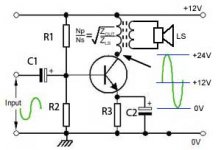
Just about everyone calls this "in phase" or "out of phase" but this is NOT phase, it is polarity. If you use an asymstrical waveform (the top half looks different from the bottom half), the difference between phase and polarity becomes clearer.Remember the simple amp circuit I posted earlier (see attachment)?
Notice how the output is out of phase with the input.
This should make no audible difference.
- Status
- This old topic is closed. If you want to reopen this topic, contact a moderator using the "Report Post" button.
- Home
- Member Areas
- The Lounge
- different audio forum