Wow, that's cooked!
A few years ago one of my GM70 amps (1kV plate V) started making ominous popping noises during use. I figured something was about to fail. Pulled apart the supply for the offending unit and discovered I had at least two 450V electrolytics on the verge of venting. These were wired 3 in series with 170K 2W equalizing resistors across them, each was dissipating a little over 600mW and was rated at 450V, and 5 of the 6 used in the PSU were OPEN!
I replaced all of the caps and resistors (different resistors) about 5 years ago and so far so good. I have 1300V 70uF films (Clarity and no longer available) to replace the stacked electrolytics but have not got around to doing it just yet.
It's pretty amazing how far things can be off before they it's really obvious in some cases.
I've only seen sweep tubes in old TVs melt their envelopes that way, I had a zenith that had a horizontal sweep tube that was about to do that, I saw it glowing madly - bad coupling cap. Replaced cap and tube and all was well - this is what I get for using an ancient VT set in the early 1980s lol.. Great for watching the B&W comedies I favored for late night viewing at the time...
I've only seen sweep tubes in old TVs melt their envelopes that way, I had a zenith that had a horizontal sweep tube that was about to do that, I saw it glowing madly - bad coupling cap. Replaced cap and tube and all was well - this is what I get for using an ancient VT set in the early 1980s lol.. Great for watching the B&W comedies I favored for late night viewing at the time...
I've only seen sweep tubes in old TVs melt their envelopes
At the age of 16 I got my first job as a TV repair man. One day I was working on a large color TV with an intermittent sync issue, so with the set on and acting up, I yanked the sync tube and took it to the tube tester. It showed shorts or gas or whatever those neon bulbs on the tube tester said. I dug up a new tube and headed back to the set to see the horizontal sweep tube glowing like a light bulb. I had pulled the horizontal oscillator too, the other half of the sync tube. This left the output tube with no drive and zero bias.....total meltdown occurred. Even the glass on the tube was red. I shut the set off and let it cool. As it cooled, the glass got sucked up tight to the metal plate making this neat sculpture. Unfortunately I broke it trying to get it out of the socket, since all the solder had melted and soldered the tube into the socket. Two new tubes and the TV was fixed. I have tried to duplicate that feat ever since with zero success.
The tube most easily melted in my experience is the 6AQ5 audio output tube. The cylindrical plate is only a few mm from the cylindrical glass envelope. If the tube's internals are perfectly colinear (rare) than you can crank them up to 15 watts or so of dissipation with minimal or no plate glow. A slightly misaligned tube will have a hot spot, and a poorly aligned tube will have a small spot that eats most of the power and glows even at or below rated dissipation. Operation in the red zone will soften the glass leaving a flat spot similar to the tube in Koda's picture. Continued operation in the red zone will eventually lead to these tubes "sucking air" and dying.
Hahaha, only the other day, 6P6S and 6P1P-EV....
Something about dissipation, mutter, grumble, 15 Watts no problem...et cetera.

I have a 6P30BR somewhere with a very bent looking anode caused by a mishap with a cathode bypass capacitor.
Some idiot put it in backwards
Something about dissipation, mutter, grumble, 15 Watts no problem...et cetera.
I have a 6P30BR somewhere with a very bent looking anode caused by a mishap with a cathode bypass capacitor.
Some idiot put it in backwards
Last edited:
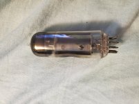
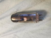
Nice and sturdy little tube.. does it still work? flash getter looks good, at least..
Mine was a 6P43P and It was way over 15 watts
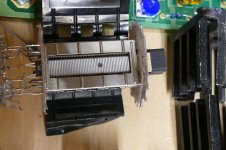
LT4320 active bridge chip destroyed last week because of the stupid mistake trying to measure scope waveforms on this wobbling setup, to check if the rectifiers worked correctly.
Sadly the probe touched something else. You simply don't work on a wobbling board at 2AM.
7$ chip in the bin, but the mosfets are intact.
Sadly the probe touched something else. You simply don't work on a wobbling board at 2AM.
7$ chip in the bin, but the mosfets are intact.
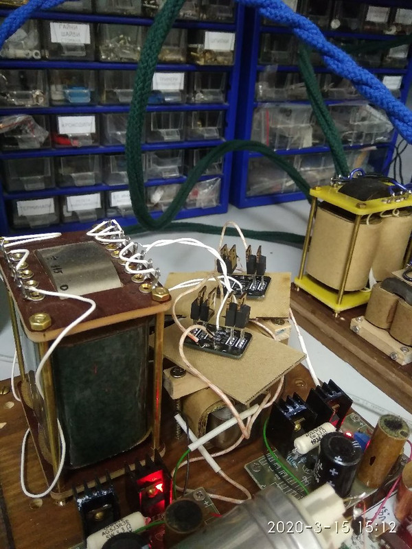
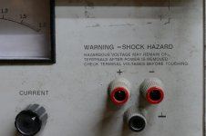
In order to design and test high powered tube stuff, I needed a big power supply. I got this one in exchange for a few hours work testing and fixing the rest of the surplus test equipment that came in the lot with this. It is an old HP6448B 1KW 60 Hz switcher, rated at 0-600V and 0-1.5A. It's basically a triac light dimmer circuit in front of a large 60 Hz transformer, rectifier CLC filter circuit. The C's are 500 uF each so there is LOTS of stored energy in the output circuit at high voltage. The feedback loop is slow, about 1 Hz corner, so that the current limiting kicks in shortly after your DUT has been vaporized!
It has made things like caps, resistors, and PCB traces disappear. So the Big Dumm Blonde One has been using it for curve tracing vacuum tubes. The BDBO makes a simple error in arithmetic and subjects a 24 watt TV sweep tube to 400 watts instead of 40. It EXPLODES, taking several other parts in the circuit with it. So, what does Big Dummy do? He tries it again! This time the tube doesn't explode, it just cracks.
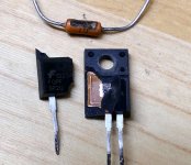
The first picture is from the first tube that exploded. It wasn't as broken as this, but it came apart when I pried it out of the socket. The guts looked OK, so I bent back the plates to look inside. A tube arc had eaten a small hole in the cathode. The mosfet feeding the screen was blown in half and a chunk was taken out of the cathode current sampling resistor.
Tube #2 obviously experienced a LARGE pulse of current through the plate pin since the glass cracked at pin 7 and spread out from there.
My name is power supply, I am HUNGRY....FEED ME
It has made things like caps, resistors, and PCB traces disappear. So the Big Dumm Blonde One has been using it for curve tracing vacuum tubes. The BDBO makes a simple error in arithmetic and subjects a 24 watt TV sweep tube to 400 watts instead of 40. It EXPLODES, taking several other parts in the circuit with it. So, what does Big Dummy do? He tries it again! This time the tube doesn't explode, it just cracks.
The first picture is from the first tube that exploded. It wasn't as broken as this, but it came apart when I pried it out of the socket. The guts looked OK, so I bent back the plates to look inside. A tube arc had eaten a small hole in the cathode. The mosfet feeding the screen was blown in half and a chunk was taken out of the cathode current sampling resistor.
Tube #2 obviously experienced a LARGE pulse of current through the plate pin since the glass cracked at pin 7 and spread out from there.
My name is power supply, I am HUNGRY....FEED ME
Attachments
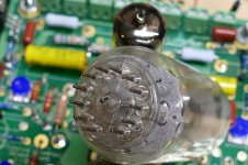
Nice and sturdy little tube.. does it still work? flash getter looks good, at least..
It did
It wasn't as strong though.How does such a BDBO find jobs?
He shows up at a Motorola plant one day in 1972, in response to a newspaper "technician wanted" advert, gets hired to work on the assembly line. 41 years and two college degrees (paid for by Motorola) later he retires as a Principle Staff Engineer in the research department.
BDBO was the term I used for myself when attempting to get through the thick heads of management in a Dummed Down manner.
There was a particular manager who was operating well above his competence level (and 4 pay grades above me) that was in charge of generating the radio level block diagrams that the software guys needed to write the code for the controller. This prototype would be built with currently available components, but had to be code compatible with the future breadboards and eventual product, so the minimal code changes would be needed as the sections were integrated into custom IC chips.
He couldn't handle that task, and I was too busy actually designing the prototype radio, so I made pencil sketches, scanned them, and emailed them to him, so he could draw them up in Powerpoint.
Here is one for the VCO section of the Frequency Generation Unit.
Attachments
<snip>
He couldn't handle that task, and I was too busy actually designing the prototype radio, so I made pencil sketches, scanned them, and emailed them to him, so he could draw them up in Powerpoint.
Here is one for the VCO section of the Frequency Generation Unit.
Ouch, I looked at the FGU drawing, not hard to grasp in about 2 seconds.. I worked with a guy not too many years ago who must have been a close cousin of that manager.
not hard to grasp in about 2 seconds.
Hence the BDBO name and the caption that went along with it.
Technically he was the lead engineer on a project that I was farmed out to. It was his responsibility to draw up the top level diagram give each interconnect a name, and fill in the basics of each block. Every signal that needs to be controlled by the CPU gets a name and a state diagram. That Frequency Generation Unit diagram is only half of the FGU picture. The other half (synthesizer and two speed loop filter) was lifted from an existing product.
He kept feeding me trash for a couple weeks, culminating in me ripping one of his diagrams up in front of him and his manager.
The resulting chest thumping session got ugly and after failing to get myself excused from the project, I was given the authority to design the stuff myself. It is now a shipping product, albeit in a much more highly integrated form. The entire FGU, most of the receiver, and all the low level transmit stuff in inside one custom IC.
We were in the midst of a serious parts shortage and just because a data sheet exists, does not mean that you can actually get the parts.
Motorola had huge buying power when we were one big happy company. Once the cellular division was separated, and then sold, that million units per month buying power became, "where is the Digikey catalog." It's hard for some old school bosses to grasp that concept.
To the local electronics recycler we have every few months
In the big box on a pallet with a couple of guys we just dumped them in. So sad
1 Barco 1208 crt
1 Ampro 4300 crt
1 NEC 6pg +
All had great tubes and just needed the room
I had already gotten rid of a NEC xg 1351 which was one my favorite home theater projectors for many years.
Never thought I would be destroying them but nobody wanted them for free either..,
In order to design and test high powered tube stuff, I needed a big power supply. I got this one in exchange for a few hours work testing and fixing the rest of the surplus test equipment that came in the lot with this. It is an old HP6448B 1KW 60 Hz switcher, rated at 0-600V and 0-1.5A. It's basically a triac light dimmer circuit in front of a large 60 Hz transformer, rectifier CLC filter circuit. The C's are 500 uF each so there is LOTS of stored energy in the output circuit at high voltage. The feedback loop is slow, about 1 Hz corner, so that the current limiting kicks in shortly after your DUT has been vaporized!
It has made things like caps, resistors, and PCB traces disappear. So the Big Dumm Blonde One has been using it for curve tracing vacuum tubes. The BDBO makes a simple error in arithmetic and subjects a 24 watt TV sweep tube to 400 watts instead of 40. It EXPLODES, taking several other parts in the circuit with it. So, what does Big Dummy do? He tries it again! This time the tube doesn't explode, it just cracks.
The first picture is from the first tube that exploded. It wasn't as broken as this, but it came apart when I pried it out of the socket. The guts looked OK, so I bent back the plates to look inside. A tube arc had eaten a small hole in the cathode. The mosfet feeding the screen was blown in half and a chunk was taken out of the cathode current sampling resistor.
Tube #2 obviously experienced a LARGE pulse of current through the plate pin since the glass cracked at pin 7 and spread out from there.
My name is power supply, I am HUNGRY....FEED ME
I have an old (Buechler, if that's how it's spelled) electrophoresis power supply that works about the same way. 0-1kV, 0-250 mA. Some day I'll get around to that project. It works, but it could use some new caps and a good cleaning to remove all the stickers put on it by the surplus dealer. Unlike your power supply though, it doesn't have very much output capacitance so it has something like 3-5 volts of ripple on the output.
BDBO was the term I used for myself when attempting to get through the thick heads of management in a Dummed Down manner.
I understand.. Some heads are just impermeable. I ended up being a freelancer because of it.
But, it's how the world works. It needs thickheads too.
- Home
- Member Areas
- The Lounge
- What did you destroy today?