Oh, the reason we go round and round is simple. We are tired old farts with nothing better to do, and let’s be completely honest with ourselves here (totally in other words) we have no other place to go! Admit it! Wives are bored to death with it eg ‘ Hey hear this honey, doesn’t it sound just great?’ ‘Yes dear, wonderful’. Zero engagement, stock placative answer. Shut the old fart up, job done, I can get back to my TV show or my book and he can go back to groping around in his CD or vinyl collection.
If you go on Facebook and start sprouting this audio stuff, you get sideways glances from family and friends. Audiophiles, and especially the DIY kind, are considered part of the crazy crowd. You know, flat earthers, alien abduction candidates, spontaneous combustion and the rest of it.
We can’t go onto a site where they are discussing serious physics because for the most part, other than a few individuals (like Dan for example who has an inside track on this quantum physics stuff like Jack Bybee) we are not bright enough or intuitive enough so we congregate here. As one audio reviewer remarked a few years ago, we are part of the ‘sad old bastards’ club. And he is absolutely correct. Go to any audio show and you will see. Half the guys are deaf. At a recent show , one old guy sitting next to me said ‘wow, sounds fantastic’. The music stopped and I spoke to him and he said ‘ can you speak up, I’m quite deaf’.
Oh, one final point. We are all very, very serious people.
😉
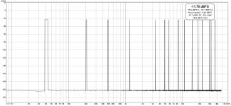
Yes, very hard to judge what is the cause of the rather small increase in the 0dBFS plot.The topic of noise modulation in DACs came up a while ago. Looking at application notes for the AK4497, I stumbled across Figures 35. and 36.
https://www.akm.com/akm/en/file/ev-board-manual/AK4497EQ.pdf
Visible is a rise of the noise floor between 1k@0dBFS and -60dBFS. The difference is small and cannot be attributed to the DAC without investigation of other possible sources.
------------------------------
FWIW, it seems I've found a phenomenon with AK4490 (of my RME Adi-2 Pro FS) that might be some form of noise-floor modulation. Between around -30dBFS and -50dBFS I see an increase of harmonics and mirrored harmonics in the upper frequency range. If one were to factor in these in a wideband THD (sans noise) measurement we would have a mid-level THD rise (not unlike the ESS chips) even when the low components stayed completely the same, because at higher levels the HF components get lower and lower in level and get spread out in frequency range, and at lower levels they get shifted higher and higher in frequency, hence making less of a contribution. Actually, only a hint of H2 was visible, and always lower in level than this new dirt.
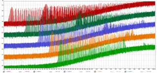
See attached plot, a loopback measurement (348kHz SR, 512k FFT, 32 averages). Shown is a 300Hz signal at levels from -34dBFS to -42dBFS. Traces have been separated by 10dB for visibility, center trace has no offset. ADC runs at 20dB gain to eliminate its influence (DAC level +24dBu, ADC level +4dBu). ADC is not the culprit, double checked with analog generator (Tek SG505). Things do *not* depend on sample rate. With other rates than 384kHz used here only the left side of the plots is truncated, otherwise no change. Frequency also doesn't matter much (and don't need to be bin-centered. If it's not a bin-center, FFT needs window which raises processing noise floor). With higher freq the spacing gets wider and the onset of the mirrored components is more readily visible (see below). Wider spacing means less total energy, therefore the effect is worse at lower frequencies.
The really interesting things is that the error spectra get heavily shifted around in frequency, especially the start of the error components, with rather moderate level changes of 2dB.
Also, we can see at -42dBFS the needles are all equally spaced at 300Hz intervals. At the higher levels, as second train of needles appears in the right-hand area of the plots which are 300Hz-spaced, but not on 300Hz multiples -- looks like mirrored at the sampling frequency (clearly visible when zoomed in and/or using higher test freq).
Not shown, I made further observations: If the test signal is not a pure sine, components start to reduce quickly. Even when a second tone (of arbitrary frequency, but preferably lower and unrelated) is 60dB down to the main tone, the hash disappears. DC level send to the DAC matters as well (which puts the modulator into a different operating point), as soon as the DC is higher than ~ -30dBFS, the needles go away).
Of course, all the dirt is way below RMS noise floor, also we don't have 100% pure sine content in any music, so it's possibly completely inaudible... but actually we don't know...
Attachments
Last edited:
IIUC, what is shown are the residuals which you have separated in 10 dB increments to ms,e them more visible.
Is this not computational errors?
Is this not computational errors?
Nope.
I have rerun the experiment several times of transferring two copies of the same wav file to a thumb drive and have found them to sound different in blind testing with witnesses.
Nobody on here could hear a difference.
All good points but none of them are relevant here. There were two bit-identical files and, unsurprisingly, they sounded exactly the same.if the source during playback is a USB stick and there is other activity on the USB buss there can be issues. Usually they are not subtle but anything from increased noise radiation to data collisions since the USB is not a priority on the buss. A standard USB audio device would be but some USB audio implementations are not isochronous and suffer for it. This is all really simple stuff to identify and isolate. I would not play from a USB stick if there is another option (and I would prefer a PCI sound card for its deterministic interface as well. . .). Could different parts of the USB memory device sound different? Maybe they too can have different noise profiles depending on how the USB device manages its internal memory. But move the data to the host PC and try again for the "same" differences. Or set up to measure the radiated EMI/RFI noise during the different playback cycles.
(Max claims that some listeners claimed to hear a difference, and I believe him. All of them were in his presence at the time. Make of that what you will.)
No (just graphics shifted), but I'm not completely clear what you mean by computational errors. REW's FFT uses 64bit floating point and its input stream is 32bit floats so the spectrum of the test signal itself is clean down to -200dB...IIUC, what is shown are the residuals which you have separated in 10 dB increments to make them more visible.
Is this not computational errors?
https://www.akm.com/akm/en/file/ev-board-manual/AK4497EQ.pdf
Visible is a rise of the noise floor between 1k@0dBFS and -60dBFS. The difference is small and cannot be attributed to the DAC without investigation of other possible sources.
My money's on that being down to dynamic range limitations in the AP's ADC. Most likely some (many?) of the visible spurs are from the ADC too, at 0dBFS. If they re-made that 0dB FFT with the 1kHz fundamental notched out, I am betting the noise floor shift will be too small to be noticeable.
Yes, very hard to judge what is the cause of the rather small increase in the 0dBFS plot.
------------------------------
FWIW, it seems I've found a phenomenon with AK4490 (of my RME Adi-2 Pro FS) that might be some form of noise-floor modulation.
Of course, all the dirt is way below RMS noise floor, also we don't have 100% pure sine content in any music, so it's possibly completely inaudible... but actually we don't know...
I set up the 4490 demo board and can see some of that with a 44.1 KHz and 48 KHz source. It all over the systems cutoff in this case. I'm driving from an Altor generator so no PC in the middle. its all way down and I'm not sure its not in the rest of the hardware I'm using but unlikely. I would need to do a lot of fiddling to drive via I2S to get to 384 KHz sampling and I'm not too inclined. The issues of idle tones around zero are not new and maybe this system fixes them by kicking them all above the audio band. I have too many other projects in the way to do this but you could learn a lot more by looking at the chips output in front of the filter. That may not be easy to access on the RME. If you look at the spectrum above the sample rate (way above) you can see why I'm not excited about using opamps as filters for this stuff.
All this suggests a really good reconstruction filter is necessary.
Because they were never completely resolved is the answer. Mere mention of BQP raises blood pressures and emotions from those who have never seen, held or heard a BQP but they sure know all about them and know how they cannot work. Proper scientific method would be to collect and discuss all the information that is available but nope the usual 'flat earth' respondents cling to their belief systems and steadfastly defend their beliefs to the death with vitriol and denigration. The above described are analogous to a virgin telling the experienced all there is to know about sex.....reading texts, watching videos, discussion with other virgins etc and everything except for the real thing. I am not raising these points in defense of BQP but I am challenging the belief systems of those who are so overwhelmingly opposed to the concept that electrical energy flow can be 'filtered' and that electricity has 'properties' that can be altered. We all learn Ohms Law and Thevenin's Theorem that predict circuit behaviour at the highest level but say nothing about lower level behaviours....this is the disconnect that the 'believers' cannot grasp it seems.Because we have short memories? Because they are controversial topics, and that makes them fun to argue about?
Dan.
In the name of scientific method please provide precise examples and justifications of your accusations of each of the categories you state above.Then why do you keep sharing unscientific, anti-scientific, and pseudo-scientific posts from unreliable sources? There is nothing scientific about that.
So the file differences supposedly did not survive upload/Dropbox storage/download process to your PC, this was a casual test with no controls like how good is your hearing and how good is your system.All good points but none of them are relevant here. There were two bit-identical files and, unsurprisingly, they sounded exactly the same.
There were numerous experiments and listeners responded with same/similar descriptions of these differences without coaching of any kind.Max claims that some listeners claimed to hear a difference, and I believe him. All of them were in his presence at the time. Make of that what you will.
I posted a link to Test Dept files a few posts back.....can you hear the differences ?.
Dan.
Last edited:
Because they were never completely resolved is the answer. Mere mention of BQP raises blood pressures and emotions from those who have never seen, held or heard a BQP but they sure know all about them and know how they cannot work. Proper scientific method would be to collect and discuss all the information that is available but nope the usual 'flat earth' respondents cling to their belief systems and steadfastly defend their beliefs to the death with vitriol and denigration. The above described are analogous to a virgin telling the experienced all there is to know about sex.....reading texts, watching videos, discussion with other virgins etc and everything except for the real thing. I am not raising these points in defense of BQP but I am challenging the belief systems of those who are so overwhelmingly opposed to the concept that electrical energy flow can be 'filtered' and that electricity has 'properties' that can be altered. We all learn Ohms Law and Thevenin's Theorem that predict circuit behaviour at the highest level but say nothing about lower level behaviours....this is the disconnect that the 'believers' cannot grasp it seems.
Dan.
Understood. You are not a virgin.
The issues of idle tones around zero are not new and maybe this system fixes them by kicking them all above the audio band. If you look at the spectrum above the sample rate (way above) you can see why I'm not excited about using opamps as filters for this stuff.
All this suggests a really good reconstruction filter is necessary.


CFB opamps could do it with some passive RC in front.
THx-RNMarsh
Last edited:
Yes, even a fast VFB or composite op-amp, no problem. There are lots of really fast FDAs for pipeline ADC drivers. Some have decent audio specs.
When I designed an analog fiber optic system with impulse frequency modulation 25 years ago, I had to use AD844 opamps in the 6-th order active filter. Carrier frequency was 2MHz and BW 0-300kHz (-3dB). WHEN I tried VFB opamps with SR 20-50V/us, the suppression of carrier frequency was inadequate.
Yes, the large signal bandwidth is often limited. There are some newer parts that are better, though. Also the option of a composite amp with some gain in the loop to limit the output swing of the input amp. Main problem is a lot of the newest stuff has lower max supply voltages.
Last edited:
Yeah, next time I open the RME I'll hook a spectrum analyser directly to the chip outputs. The AK4490 has a switched-capacitor filter in front of the voltage output pin that is supposed to take care of modulation and RF noise but it won't be that much effective, I fear. RME's subsequent filtering is tailored to pass 100kHz and is fixed.I set up the 4490 demo board and can see some of that with a 44.1 KHz and 48 KHz source. It all over the systems cutoff in this case. I'm driving from an Altor generator so no PC in the middle. its all way down and I'm not sure its not in the rest of the hardware I'm using but unlikely. I would need to do a lot of fiddling to drive via I2S to get to 384 KHz sampling and I'm not too inclined. The issues of idle tones around zero are not new and maybe this system fixes them by kicking them all above the audio band. I have too many other projects in the way to do this but you could learn a lot more by looking at the chips output in front of the filter. That may not be easy to access on the RME. If you look at the spectrum above the sample rate (way above) you can see why I'm not excited about using opamps as filters for this stuff.
All this suggests a really good reconstruction filter is necessary.
Those tones I saw can actually go way below 20kHz with some combinations of frequency and level, so it doesn't seem AKM did some form of shaping to have those tone strictly above audio band, or at least it is not fully effective.
I'm still puzzled and have no idea what the root cause is, and it might as well be a systems thing specific to the RME, some form of crosstalk or whatever.
Ashley Monroe’s time with the Pistol Annie’s was noteworthy.
YouTube
That's great MB. I believe they are going to do more work together.
Love the harmonies and that swampy, tremolo baritone guitar.
Yes, very hard to judge what is the cause of the rather small increase in the 0dBFS plot.
------------------------------
FWIW, it seems I've found a phenomenon with AK4490 (of my RME Adi-2 Pro FS) that might be some form of noise-floor modulation. Between around -30dBFS and -50dBFS I see an increase of harmonics and mirrored harmonics in the upper frequency range.
If one were to factor in these in a wideband THD (sans noise) measurement we would have a mid-level THD rise (not unlike the ESS chips) even when the low components stayed completely the same, because at higher levels the HF components get lower and lower in level and get spread out in frequency range, and at lower levels they get shifted higher and higher in frequency, hence making less of a contribution. Actually, only a hint of H2 was visible, and always lower in level than this new dirt.
KSTR, thanks for posting this, I have the same piece of kit so I read it with double interest.
All the hash appears to be outside the audio band, so could this be the noise shifting filter inside the DAC moving around quantization errors into ultrasonics?
- Status
- Not open for further replies.
- Home
- Member Areas
- The Lounge
- John Curl's Blowtorch preamplifier part III