AHB2 power amp has very low distortion even at 100mw of power due to the class-A feedforward. I doubt high wattage class-D designs can do that at this point. It matters to me because I like to be able to operate the amp over a wide range of volume levels.
For the bulk of the market class-D seems likely the way to go. Probably be awhile before the best of what Bruno can do today filters down to commodity products however.
Sorry, I meant efficiency only, not in audio performance.
Yeah, I am sure the market below ultra high-end will be dominated by the TI and ST Micro chip amp offerings.
Here is a serious study of sensitivity to ultrasonic sound: https://asa.scitation.org/doi/10.1121/1.5063818
Its not about audibility of ultrasonics in recordings but shows the extent of effort and complexity necessary to do a proper human perception sensitivity test. And seems to show humans are not sensitive to sounds at 20 KHz or at least they have very little effect.
Its not about audibility of ultrasonics in recordings but shows the extent of effort and complexity necessary to do a proper human perception sensitivity test. And seems to show humans are not sensitive to sounds at 20 KHz or at least they have very little effect.
> How about a headphone driver that draws 100W quiescent?
We are getting close :
Dynamic phones, 22~50W
Pro iCAN by iFi audio | Professional Studio Grade Headphone Amplifier
Dynamic phones, 54W Class A
https://www.diyaudio.com/forums/hea...ss-zgf-headphone-amplifier-7.html#post5405088
post #331
+/-24V 400mA per channel
ESL phones, 180W
HeadAmp Blue Hawaii Special Edition Electrostatic Headphone Amplifier
ESL phones, 79W
KGSSHV Carbon amplifier for STAX - open-end-music-professional
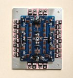
My still-under-construction +/-400V XAESHA based on Blowtorch topology, 82W
(See photo).
🙂
Patrick
.
We are getting close :
Dynamic phones, 22~50W
Pro iCAN by iFi audio | Professional Studio Grade Headphone Amplifier
Dynamic phones, 54W Class A
https://www.diyaudio.com/forums/hea...ss-zgf-headphone-amplifier-7.html#post5405088
post #331
+/-24V 400mA per channel
ESL phones, 180W
HeadAmp Blue Hawaii Special Edition Electrostatic Headphone Amplifier
ESL phones, 79W
KGSSHV Carbon amplifier for STAX - open-end-music-professional
My still-under-construction +/-400V XAESHA based on Blowtorch topology, 82W
(See photo).
🙂
Patrick
.
Attachments
The numbers are there on the link that has been posted on here at least twice. Mostly noise TBH. And it shouldn't matter when the artifacts are below 0dBA.AHB2 power amp has very low distortion even at 100mw of power due to the class-A feedforward. I doubt high wattage class-D designs can do that at this point. It matters to me because I like to be able to operate the amp over a wide range of volume levels.
.
Here is a serious study of sensitivity to ultrasonic sound: https://asa.scitation.org/doi/10.1121/1.5063818
Its not about audibility of ultrasonics in recordings but shows the extent of effort and complexity necessary to do a proper human perception sensitivity test. And seems to show humans are not sensitive to sounds at 20 KHz or at least they have very little effect.
Does appear some of the participants are sensitive to thinking that ultrasound is present. Just like the people "allergic" to Wi-Fi, but only when they think it's present.
Well that seems like a plausible explanation for the ‘settling’ .... and now that it’s mentioned the sound during the settling period is much the same as that of not being warmed up sufficiently.
But there’s still the differences in other wire types after that fact 😀
Mark seems overly keen on reinforcing your bias that you are not susceptible to expectation bias or confirmation bias and probably others which are evident in your posts.
BS....... Just like the people "allergic" to Wi-Fi, but only when they think it's present.
Electrosensitivity from a neurological point of view
Electrosensitivity is a product of "deficiency in essential elements and an overload in toxic elements, genetic polymorphysms and hypersensitivities against heavy metals."
Dan.
So just what is causing the correlation then Bill, you seem to know all about it.
Dan.
Heavy metal poisoning has been known to create paranoia in subjects. So it's equally credible to pontificate that electrosensitive types have other issues.
BS.
Electrosensitivity from a neurological point of view
Electrosensitivity is a product of "deficiency in essential elements and an overload in toxic elements, genetic polymorphysms and hypersensitivities against heavy metals."
Dan.
You should try getting medical advice from (real) doctors or at least legitimate medical journals rather than from crazies on Google Groups.
Are you an anti-vaxxer too? Wouldn’t be surprised, seems to be popular with the tinfoil hat crowd.
Give it a break Chris, so that you are abundantly clear I am not of the tinfoil hat crowd, or 'conspiracy theory' or anti-vaxxer or ufo/aliens believer or anti-Einstein or whatever colour you wish to paint me, I am fully scientific in my outlook and yes valid proofs are the result of good science.Are you an anti-vaxxer too? Wouldn’t be surprised, seems to be popular with the tinfoil hat crowd.
That said there are plenty of examples of bad science and research findings that are later disproved or proven fraudulent.
You brought up the subject of EMR 'allergy', this is of concern as the likes of 5G transceivers are set to become ubiquitous throughout home, work and environment. There is more to EMR sensitivity than meets the eye it seems and full understanding of biological effects of man made EMR is lacking at this point in time.
Dan.
That link gave no idea as to whether the tests were blind or not, either.
It was a presentation at a congress and according to the short description in the abstract, the EEG and brain mapping were done most likely non-blind, although it might have been single-blind.
EEG and brain mapping was performed as a baseline and in the presence of a cellphone held to the ear (but not talking), blood pressure and pulse were measured every 5 minutes with an automated blood pressure machine.
I'd call that sighted?
You should try getting medical advice from (real) doctors or at least legitimate medical journals rather than from crazies on Google Groups.
<snip>
I'd like to see some evidence for your (implicite) assertion that this journal is not a "legitimate medical journal" .....
It is also illuminating thatI'd like to see some evidence for your (implicite) assertion that this journal is not a "legitimate medical journal" .....
....this includes Lloyds Of London.In our reporting for this story, we found not a single insurance company that would sell a product-liability policy that covered mobile phone radiation.
Dan.
It seems this is what some people hear when someone else tells them that a technical viewpoint they are putting foward is incorrect. This is people who believe that they have good hearing yet when someone says "you are mistaken" what they hear is "you are crazy and have a small d***".RNMarsh said:yes, fer sure.... some will threaten your manhood. Some will tell you, you are crazy or worse.
We take them seriously enough to dispute some of what they say on technical issues. We continue to be surprised that people with such experience can have such glaring holes in their understanding of electronics.mountainman bob said:Many of the things you fellers dismiss do in fact matter, but I’m not gonna become the new sideshow especially when the likes of Marsh and Curl can’t even be taken seriously.
Having now seen the circuit, I am going to hazard a guess that what you heard was not the resistor quality (which would only affect LF) but the stray capacitance of the 2M2. Unless, of course, you allowed for this by adjusting circuit strays as you swapped resistors.morinix said:The resistor I had to change is the one labled 2M2 (221k in my circuit though). My version has 40db of gain so everything is magnified. At that kind of gain the 2M2 position plays a much bigger part in the quality of the high frequencies than one would think. This is in spite the corner frequency being at about 200hz!
It wan't my claim, but one I understand. If you wish, contact Hans van Maanen via the Temporal Coherence website. His use of the 'temporal' word is his, not mine. But basically when the amp transitions from Class A (both devices 'on') and Class B (one device goes 'off') and the voltage and current (the current phase angle no longer matches the voltage) are no longer 'temporal' time wise, his claim is that the feedback loop will respond in such a way that you will get high order distortions and I believe he claims he had not only examined the mechanism and used measurements to prove it.
Joe, you have mentioned possible problems of class AB amplifiers when driving a complex inductive load. I was very skeptical to this, as I have had no bad experience like that and operational class of the well designed amplifier did not seem to have any special effect to clean complex load driving ability, to me.
However, something strange happened to me. I was measuring 2 preamplifiers, with basically same circuit design (complementary differential JFET input + folded cascode VAS + output stage) which were different only in the output stage circuit.
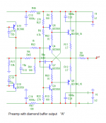
Preamplifier “A” has a diamond buffer based output stage, with output impedance 50 ohm (series resistance).
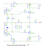
Preamplifier “B” has a conventional NPN-PNP simple EF output stage, with output impedance 50 ohm as well (series resistance).
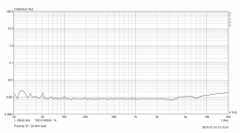
Both preamps measure almost identically into 10k resistive load and both are able to drive 50 ohm load with low distortion, “B” being little worse but still keeping THD in order of 0.001%.
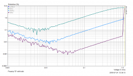
Now, I tested both “A” and “B” with a link level output transformer, which a primary Rs = 40 ohm, Ls = 4H, secondary Rs = 70 ohm and secondary Ls = 4H. This transformer has of course increased distortion at low frequencies and I have measured it dozens of times.
But, what happened now. Though preamp “A” shows “standard” distortion plots with the transformer, preamp “B” has enormous rise of distortion numbers. A reminder, it drives a resistive load down to 50 ohms with no problems.
Attached are circuits of output stages “A” and “B”, measurements of distortion (at 50Hz, 200Hz and 1kHz) into link transformer with preamps “A” and “B” and also a measurement of the suspicious preamp “B” into 50 ohm resistive load.
Anyone with a meaningful explanation?
P.S.: 1V is the input range limit in these measurements
Attachments

Last edited:
- Status
- Not open for further replies.
- Home
- Member Areas
- The Lounge
- John Curl's Blowtorch preamplifier part III