Perhaps I can use it to discriminate the Goop loopback recordings changes that Mountain Bob hears.
.
I’d be curious, but you’d have to go off previously tested tracks.....my system is packed up while I finish the part of the house it occupied.
Going to be 2 or 3 months before it’s back....and there’s going to be much testing afterwards as it will be a new room with some new components including speakers/xo.
Bob
Yes, the comparisons would be using the existing recordings.I’d be curious, but you’d have to go off previously tested tracks.....my system is packed up while I finish the part of the house it occupied.
Three months, ouch.Going to be 2 or 3 months before it’s back....and there’s going to be much testing afterwards as it will be a new room with some new components including speakers/xo.
I had a close look at your Parasound amp and I think there are easy improvements to be made.
Dan.
Bring it Dan! All input is appreciated
When I put everything back together I’ll be setting up the system in its original tune and using it as reference for the new stuff.....ought to be fun (probably not so much for the wife!)
Vac I detect a bit of sarcasm there but what I gleaned from the bits of info I did get from JC (whether direct or indirect) there were things about the Hint that happened in production that weren’t to his liking......I suppose that happens in the design world all the time?
I just lost a long post but the gist is I respect JC's electronic design and Parasound's layout/physical design and that I would change out the final output cables/connectors loom assembly to different wire/banana sockets and experiment with the output parallel RC filter component chemistries and maybe values.
I would also look for ferrite series filters and consider removing them, I believe there are two on the IEC power entry pcb and possibly two on each output stage module ?.
That's for starters but that should liven things up and start to add back honest clarity/sparkle that has been nobbled by factory decisions.

Dan.
Bob, I can tell you much more in PM.") .
.
I would also look for ferrite series filters and consider removing them, I believe there are two on the IEC power entry pcb and possibly two on each output stage module ?.
That's for starters but that should liven things up and start to add back honest clarity/sparkle that has been nobbled by factory decisions.
Dan.
Bob, I can tell you much more in PM.
.I have a new listening test - 2 preamps are compared. For those who might be interested, there is a link:
Can you hear a difference between 2 solid state preamps?
Can you hear a difference between 2 solid state preamps?
Definately appreciated Dan,
Yah, if your inclined to send a detailed description of changes and what brand/type the new pieces might be I will make sure my pm box has room!
I’m not worried about warranty at this point......it came back from them with a clean bill of health as it was. ‘As it was’ isn’t exactly up to standards.....at least mine anyway.
I might add I won’t be the one doing the changes (fear of screwing it up entirely) but I’m going to try and find someone fairly close by that might not mind sharing some experience for proper compensation! I know most don’t like ‘training’ people in their craft but there could be someone that might like to help pass the torch.
Bob
Last edited:
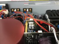
I find it interesting that you can use generic molex type tinned connectors inside the box but the ones outside need to be precious gold plated massive connections. And not just on the premium mass brands. I have seen the same schizoid thinking on some very high end German stuff. Is there something I'm missing? Are those pin connectors OK?
When I was designing the Spectral equipment 30+ years ago I made sure to parallel the gold pins and contacts in the .1" header arrays to get a really reliable low impedance connection for low level stuff. For high current we used exotic space grade stuff for board to board and to the panel connections. Using the simple Molex stuff would be much easier and cheaper. Is it really adequate?
When I was designing the Spectral equipment 30+ years ago I made sure to parallel the gold pins and contacts in the .1" header arrays to get a really reliable low impedance connection for low level stuff. For high current we used exotic space grade stuff for board to board and to the panel connections. Using the simple Molex stuff would be much easier and cheaper. Is it really adequate?
Once, long ago, I opened up a McIntosh (high end @ the time) amplifier.I find it interesting that you can use generic molex type tinned connectors inside the box but the ones outside need to be precious gold plated massive connections. And not just on the premium mass brands. I have seen the same schizoid thinking on some very high end German stuff. Is there something I'm missing? Are those pin connectors OK?
When I was designing the Spectral equipment 30+ years ago I made sure to parallel the gold pins and contacts in the .1" header arrays to get a really reliable low impedance connection for low level stuff. For high current we used exotic space grade stuff for board to board and to the panel connections. Using the simple Molex stuff would be much easier and cheaper. Is it really adequate?
The boards that could be glimpsed from the outside used 1% metal film.
The out of sight boards used 10% carbon composition.
I have seen the same schizoid thinking on some very high end German stuff. Is there something I'm missing? Are those pin connectors OK?
I have very, very bad, very bad repeated experience with the pin connectors, for audio.
I almost exclusively use Molex connectors inside the amp for the critical PCB to flying lead main power MOSFET or BJT connectors to allow for easy and flexible mounting options with heatsinks. This is especially helpful for Class A amps where a remote CPU cooler and fan can easily handle 100w to 150w dissipation from a device.
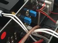
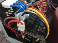
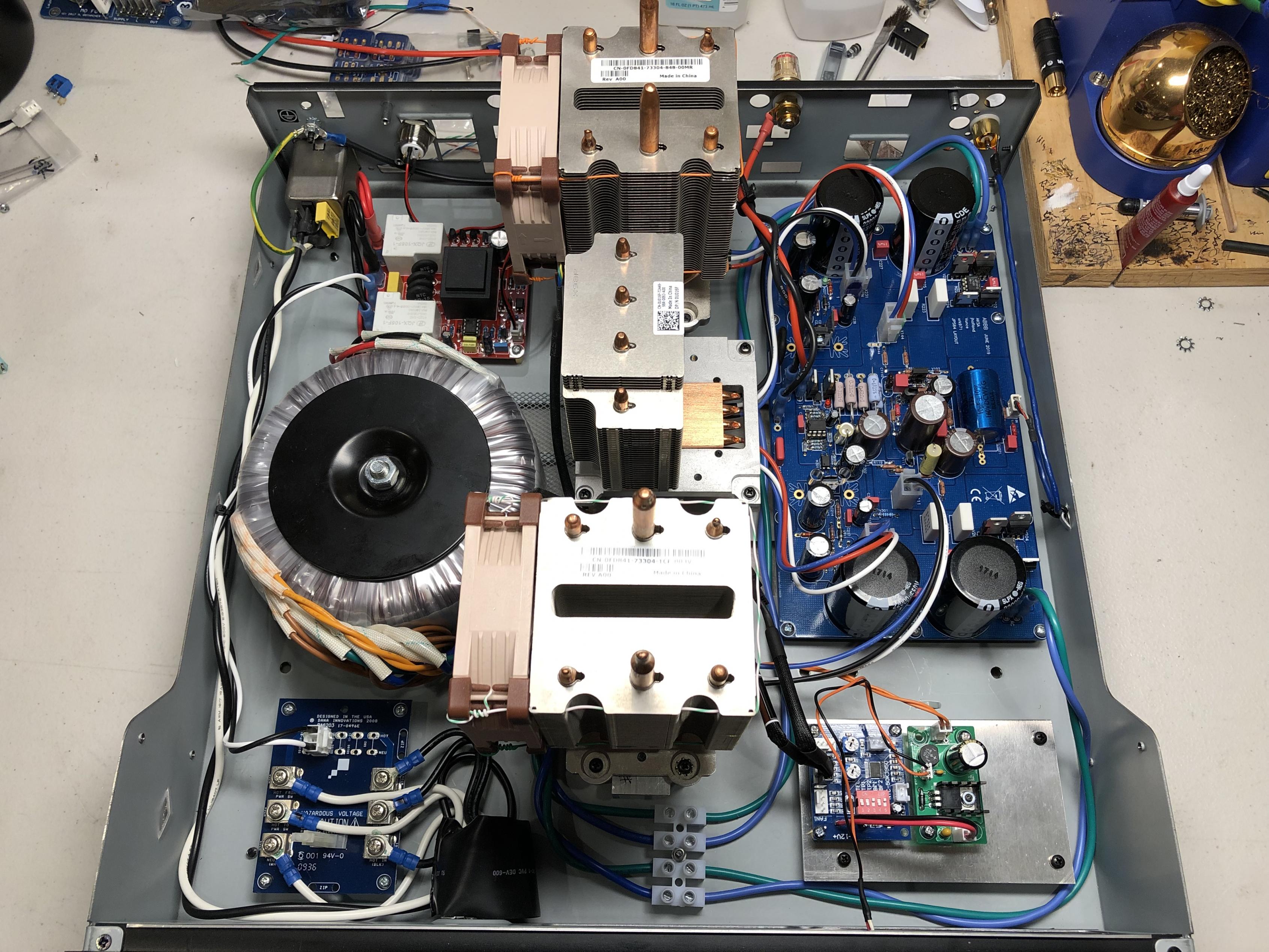
As an example, here is the ABBB amp built by Vunce. Molex 4-pin minifit Jr connectors from the PCB to the flying leads (soft silcone jacket RC car wire) and small helper PCBs on the MOSFET legs.
I am also planning on using the Molex for the flying leads on the MOSFETs for the Alpha Nirvana:
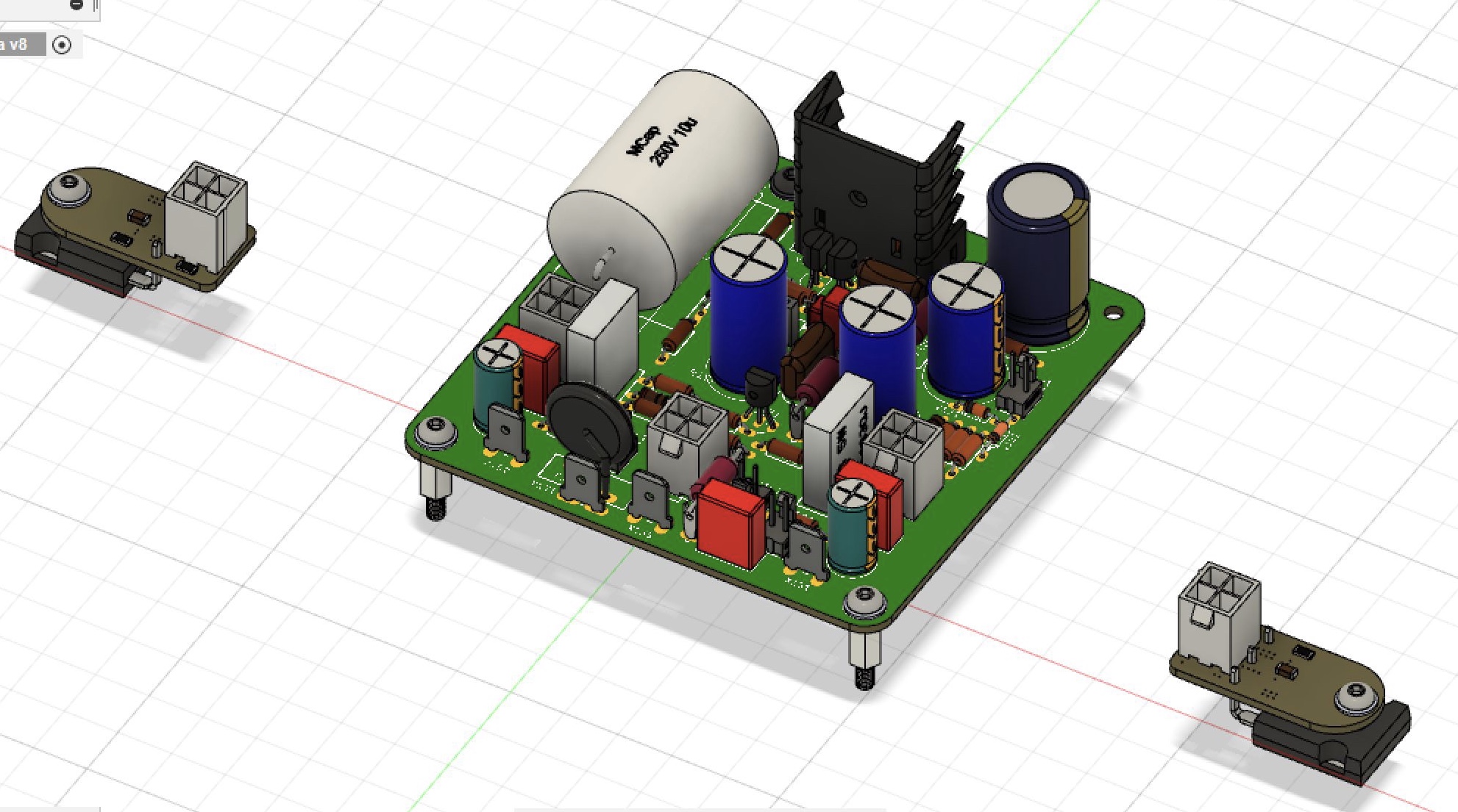
These connectors are very reliable (have a postive locking lever), are polarized to prevent mistakes, pass super high current, and make case work a snap. Also very good for maintenance and repair if you need to pull the board or just the MOSFET out.
As an example, here is the ABBB amp built by Vunce. Molex 4-pin minifit Jr connectors from the PCB to the flying leads (soft silcone jacket RC car wire) and small helper PCBs on the MOSFET legs.
I am also planning on using the Molex for the flying leads on the MOSFETs for the Alpha Nirvana:
These connectors are very reliable (have a postive locking lever), are polarized to prevent mistakes, pass super high current, and make case work a snap. Also very good for maintenance and repair if you need to pull the board or just the MOSFET out.
Easier and Cheaper are probably the key words.
Would one benefit from soldering all those connections? As long as it could be done without damaging anything.
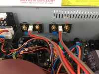
There seems to be an awful lot of protection circuit relays also.....it sounds like a robot coming to life when you power it up!
Would one benefit from soldering all those connections? As long as it could be done without damaging anything.
There seems to be an awful lot of protection circuit relays also.....it sounds like a robot coming to life when you power it up!
The ABBB uses a SSR DC protection circuit - built in, so no clicking and clacking. You may be referring to a third party slow-start circuit on the amp that Vunce made? The Molex's have been used on my other top end Class A amps and there are simply no issues. The sound quality is excellent (measures excellent too) and there are no problems with reliability. For DIY. where we sometimes need to install and remove boards from a common 'house' chassis, this is perfect. There are people who do not believe in any connectors at all - they eschew spades for PSU in and speaker out, preferring to solder the wire directly to the PCB. My issue with that is the mechanical strain on the wires. They fail eventually if removed and installed even a few times.
- Status
- Not open for further replies.
- Home
- Member Areas
- The Lounge
- John Curl's Blowtorch preamplifier part III