lose the cap?
IMO, and as at least one wag said, there is no capacitor like no capacitor. But I also recall Peter Q. dissenting on this, citing a large improvement from incorporating a coupling cap in a tube circuit where it appeared it could have been avoided.
If one is not too concerned about a modest click on unmute, I'd go ahead and lose the 100uF and the 47k and just leave the series 100 ohm and muting relay. It was puzzling to read the person's lengthy account of bypassing the 'lytic with a paper and oil cap, and the purported sonic benefits.You are correct. As we say in Dutch "I wasn't looking beyond the length of my nose".
IMO, and as at least one wag said, there is no capacitor like no capacitor. But I also recall Peter Q. dissenting on this, citing a large improvement from incorporating a coupling cap in a tube circuit where it appeared it could have been avoided.
IMO, and as at least one wag said, there is no capacitor like no capacitor. .
It was something I originally said about coupling caps and then presented the idea of a dc servo. But, what I actually said was ---- The best capacitor is no capacitor.
THx-RNMarsh
It was something I originally said about coupling caps and then presented the idea of a dc servo. But, what I actually said was ---- The best capacitor is no capacitor.
THx-RNMarsh

The 100Hz multiples are there, with BJT input opamps, even if the input is shorted and no generator (no additional wires) connected to the input. So the only paths are through the air or supply.
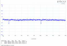
Some new measurements and new findings. The interference is definitely air coupled (inductively or capacitively). Hand waving above the test circuit significantly changes amplitude of the output interference. NE5532 is far less (1-2 orders) susceptible to this than LM4562. With NE5532, 100Hz peaks have almost disappeared but they appear with hand waving above circuit. Please review the attached measurements. Interesting is that peaks sometimes change polarity, big 100Hz peaks go positive and slow cca 10Hz smaller squares go negative.
JFET opamps do not pickup any interference. This is in conformance with general knowledge, published e.g. by Analog Devices, that BJT input opamps are at several orders more susceptible to HF interference. It is just interesting to see it in reality.
Interestingly enough the LM4562 family is very poor regarding this and to me it is enough reasoning not to use this part, even if someone would say that standard gain and careful shielding might cure this. Side be side comparison, the part will be more susceptible to interferences than other parts.
Attachments
Last edited:
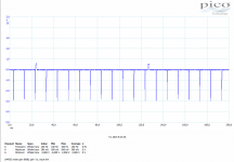
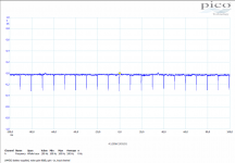
Now, BJT input opamps - and it is a completely different story. Same setup, nothing has changed, only opamps in the socket. See NE5532 and LM4562 results. For LM4562, I am attaching the time record as well, to see what is happening. The 100Hz peaks are slowly traveling along the curve shape. Together with slower, almost rectangle superimposed peak (not seen in this plot).
Should be said that AD797 and LT1028 do not have this strange behavior.
Should also be said that I have several production series of LM4562, since 2008 till about 2012 years, and all behave the same. All bought from authorized distributors.
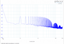
Obviously you have measured nonlinear distortion. The 100 Hz fundamental is very clear, and so the remaining spikes at multiples of 100 Hz are harmonics.
Running these op amps at gain of 10,000 varies considerably from their recommended use. If you want to run gains like these, you should be running op amps that are designed for it - they are the common types used for microphone preamps.
I think you missed the point of measuring opamps with increased noise gain. You might wish to orientate yourself further. The OPA134 specsheet is a good beginning.
Btw, Pavel's measurements coincide with my experiences working with these opamps. It is instructive to now see in more detail how these different opamps compare.
Btw, Pavel's measurements coincide with my experiences working with these opamps. It is instructive to now see in more detail how these different opamps compare.
Last edited:
I think you missed the point of measuring opamps with increased noise gain. You might wish to orientate yourself further. The OPA134 specsheet is a good beginning.
You ought to read it some time. It is mostly about what I talked about - measuring distortion. Does it suggest measuring op amps at a gain of 10,000 or more? Well, you show me - provide a relevant paragraph number.
Btw, Pavel's measurements coincide with my experiences working with these opamps. It is instructive to now see in more detail how these different opamps compare.
I don't see a lot of respect for the concept of using the right tool for the job.
If heaven forbid someone wants to see how professionals test op amps for EMI, they might want to read:
http://www.ti.com/lit/an/sboa128a/sboa128a.pdf
Not the be all or end all, but any deviations from it should be justified by the use of science and reason, not hand waving.
Obviously you have measured nonlinear distortion. The 100 Hz fundamental is very clear, and so the remaining spikes at multiples of 100 Hz are harmonics.
Running these op amps at gain of 10,000 varies considerably from their recommended use. If you want to run gains like these, you should be running op amps that are designed for it - they are the common types used for microphone preamps.
Please take into account that this last set of measurements is without any signal generator. The input is shorted with 50 ohm terminating resistor, output connected to scope. So it cannot be "measured nonlinear distortion".
I know these EMIRR sheets you are linking. What is your personal experience and background in measuring EMI? My is design of special instruments for High Voltage and High Power testing laboratories. Measurement of discharges in SF6 HV circuit breakers etc.
Last edited:
Received some questions, I will reply here.
1) It is there even if battery 2x9V supplied. So no excuses to PSU ripple.
2) Input is shorted with 50 ohm, no generator connected. It catches 100Hz from the air.
3) Three independent instruments measure the same. Oscilloscope, USB oscillosope and sound card.
I would appreciated your thoughts, but not oversimplified armchair guesses.
Attachments
Pavel,
You are confusing the folks who don't know your AC power line frequency is 50 hertz. If your measurements showed 120 hertz they would be screaming power line noise.
Also the 4562 now the LME49720 is only obsolete in the DIP package.
What takes the issue is either a small resistor or coil in series with the input. But you knew that.
ES
What takes the issue is either a small resistor or coil in series with the input. But you knew that.
ES
Maybe. And of course complete mumetal cage. My question is WHY? Why specifically this opamp, that became so popular both in amateur and professional audience? Normally, audio gear is almost always not designed with respect to EMI interference. Why not to use parts that are much more, several orders, more resistant to EMI?
Please take into account that this last set of measurements is without any signal generator. The input is shorted with 50 ohm terminating resistor, output connected to scope. So it cannot be "measured nonlinear distortion".
I know these EMIRR sheets you are linking. What is your personal experience and background in measuring EMI? My is design of special instruments for High Voltage and High Power testing laboratories. Measurement of discharges in SF6 HV circuit breakers etc.
What is the power line frequency in your area?
You ought to read it some time. It is mostly about what I talked about - measuring distortion. Does it suggest measuring op amps at a gain of 10,000 or more? Well, you show me - provide a relevant paragraph number.
I hope you had an opportunity to look at the specsheet of the OPA134 so you can answer the question about which para number yourself.
Since you couldn't derive the correct noise gain figure yourself from Pavel's schematic, I don't know if you have the right background to appreciate an explanation, but I will attempt to do so anyways.
Any deviant signal caused by EMI can be seen as an internal error source generated by the opamp. As you may be aware, this is the region where NFB is effective by referring the output to the input, and by correcting for delta's. This mechanism is not different for distortion or other internal errors such as produced by EMI. By shunting part of the feedback to ground, the noise gain can be increased without influencing signal gain. (The noise gain is determined by the ratio of the feedback that remains available for error correction, plus the signal gain, so you know for the next time). In short, increasing noise gain is a valid method to appreciate the impact of emi on the functioning of an opamp.
There is no limit to the amount of noise gain one may introduce, it depends on what the scope of the investigation is. So, 80dB is a lot, but if it is needed to show the issue at stake, what would be your problem with it?
I hope you had an opportunity to look at the specsheet of the OPA134 so you can answer the question about which para number yourself.
Of course I read it, and found nothing that you referenced.
Furthermore I asked you for a specific answer, which apparently you can't answer.
Noting that when some people are caught in errors, they blame others.
Arnyk, my answer to your remarks obviously flew right over your head. I am very sorry and will no longer attempt to educate.
I dunno, looks like there was even a figure showing the setup, design equations, and parts values for different noise gains. But what do I know, I'm just a dumb scientist, not an engineer.
Some new measurements and new findings. The interference is definitely air coupled (inductively or capacitively). Hand waving above the test circuit significantly changes amplitude of the output interference. NE5532 is far less (1-2 orders) susceptible to this than LM4562. With NE5532, 100Hz peaks have almost disappeared but they appear with hand waving above circuit. Please review the attached measurements. Interesting is that peaks sometimes change polarity, big 100Hz peaks go positive and slow cca 10Hz smaller squares go negative.
JFET opamps do not pickup any interference. This is in conformance with general knowledge, published e.g. by Analog Devices, that BJT input opamps are at several orders more susceptible to HF interference. It is just interesting to see it in reality.
Interestingly enough the LM4562 family is very poor regarding this and to me it is enough reasoning not to use this part, even if someone would say that standard gain and careful shielding might cure this. Side be side comparison, the part will be more susceptible to interferences than other parts.
Looking at your results, I more and more believe you are seeing the DUT operating for some reason in open loop mode.
The LM4562 OL gain is 2 or three orders of magnitude greater than the 5532 or 5534 so this it could be hypothesized is the difference in output level you are seeing. What is also interesting is that your circuit source impeadance are very low (10 Ohms IIRC). Surely the coupling from your hand to the inputs would reflect that?
Arnyk, my answer to your remarks obviously flew right over your head. I am very sorry and will no longer attempt to educate.
Too bad you can't answer the simple questions I asked, and instead feel obliged to launch into a personal attack.
Of course, you being an uncredentialed amateur, I was being impolite to press you for a reasoned response. My apologies.
Of course, you being an uncredentialed amateur...
So am I, yet I had no problem understanding the point and finding the relevant information in the cited datasheet. Perhaps being uncredentialed is a virtue.
- Status
- Not open for further replies.
- Home
- Member Areas
- The Lounge
- John Curl's Blowtorch preamplifier part II