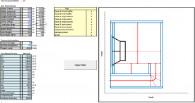
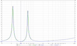
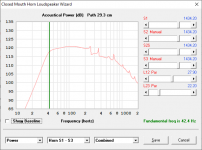
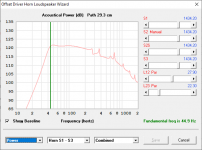
I think some of you might be interested in this - a vented and "TL" alignment modeled with the same external box size and same mouth CSA.
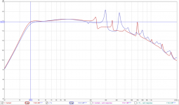
From the looks of it, the TL approach allows for better control of resonances in the midbass area, at the expense of worse performance at higher frequencies.
Hornresp also predicts at 1.5dB difference at Fb, but I'll bet that difference will be a bit smaller when losses are taken into effect.
From the looks of it, the TL approach allows for better control of resonances in the midbass area, at the expense of worse performance at higher frequencies.
Hornresp also predicts at 1.5dB difference at Fb, but I'll bet that difference will be a bit smaller when losses are taken into effect.
Attachments
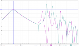
Interesting, I wonder how the other aspects differ, such as impedance and particle velocity, what is the driver Sd?
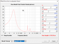
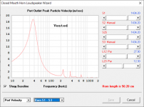
I'm trying to understand how well BR works with regards to particle velocity compared to TL at higher, or maximum, powerlevels as the mechanics behind establishing resonance is different, Helmholz vs. Qw.
I'm trying to understand how well BR works with regards to particle velocity compared to TL at higher, or maximum, powerlevels as the mechanics behind establishing resonance is different, Helmholz vs. Qw.
Interesting, I wonder how the other aspects differ, such as impedance and particle velocity, what is the driver Sd?
See comparison images attached. There are some minor differences between the two.
Attachments
Granted they are vented boxes but calling one a bass reflex and the other a transmission line?
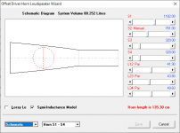
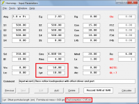
One of them is laid out and modeled as a offset-driver transmission line. The Hornresp model looks like the attached image.
Attachments
TL. and bass reflex faded into each other and lost the "TL" parts that really seem to stand out if used? thats a nice subwoofer no doubt and nothing wrong with that for sure.... always admired the boom units size and design for its use.
But if it was 117, 100 and 100 cm of 'a vas needed CSA straight or stepped up/down at node/antinode (folds there at those as well for the FB) the driver entry at the first of the two, and then the exit vent location shared as a slight rear chamber or tapped mouth with the other output as a result.
what changes? or would be an audible and interesting result. besides any size/volume gains in output(those dont count and arent fair/comparible).
I think some of you might be interested in this - a vented and "TL" alignment modeled with the same external box size and same mouth CSA.
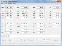
The BOXPLAN screen print for the vented system shows a port tube with Ap = 320.00 cm^2 and Lpt = 59.30 cm, meaning that a 6.19 cm end correction will be automatically added to the tube length when the simulation calculations are done. This needs to be taken into account in any such comparisons.
So, you're saying that "the bubble" will be added at one, but not the other?
When Ap and Lpt are used Hornresp assumes that a port tube is being specified and adds an internal end correction accordingly (an external end correction is not required because the radiation impedance is taken into account instead). When a horn segment is used no end corrections are added because Hornresp has no way of knowing that the horn segment is specifying a port tube.
Attachments
 appreciate it!
The BOXPLAN screen print for the vented system shows a port tube with Ap = 320.00 cm^2 and Lpt = 59.30 cm, meaning that a 6.19 cm end correction will be automatically added to the tube length when the simulation calculations are done. This needs to be taken into account in any such comparisons.
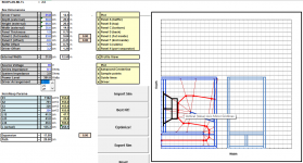
The slot-loaded design was adjusted to ensure the Fb matched the MLTL design.
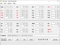
With the same physical layout simmed as both a vented and stepped MLTL design, there is a shift in Fb, as pictured below.
Which one is correct? Well, there's only one way to find out - build and measure
") .
.Attachments
Given that the last segment in the TL case is constant area one could regard it as a ported system, or at least ported in the last step, but I'm not sure what designcriteras needs to met for calling it a TL, or OD-TL, I assume that if you where to keep the negative taper all the way the result would diverge alot more and achieving the same tuning in the same volume would not be possible
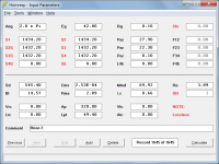
given that the last segment in the TL has a constant area, similar to the BR but simulated as a hornsegment no end correction is applied
Correct, but remembering that it is only the "internal" end of the segment that does not have a correction applied.
With the same physical layout simmed as both a vented and stepped MLTL design, there is a shift in Fb, as pictured below.
This sounds vaguely familiar to a previous comparison exercise you did. Could you please post the complete inputs for both designs. Given that they are physically the same I am interested to see why there should be a difference in results if the end correction is taken into account.
Given that the last segment in the TL case is constant area one could regard it as a ported system, or at least ported in the last step, but I'm not sure what designcriteras needs to met for calling it a TL, or OD-TL, I assume that if you where to keep the negative taper all the way the result would diverge alot more and achieving the same tuning in the same volume would not be possible
Technically it's a OD-MLTL (mass-loaded transmission line), but really there's nothing in the definition of a TL that says that the expansion has to be tapered or straight or some combination of the two.
This sounds vaguely familiar to a previous comparison exercise you did. Could you please post the complete inputs for both designs. Given that they are physically the same I am interested to see why there should be a difference in results if the end correction is taken into account.
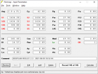
See sims attached. I added a very thin segment to the ODOV sim to bring as close as possible to the OD system.
Attachments
- Home
- Loudspeakers
- Subwoofers
- Vented vs TL...