I have mulled this idea over in my head for a long time, and I thought I would bounce it off of forum members to get feedback and suggestions.
I like to use large H-frames as dipole subwoofers for my OB/dipole speakers. But as the size of the 'frame gets larger and larger, they start to take up a lot of space and project out into the room. For example, I currently have a 1m deep H-frame having a cross section of about 0.6x0.6m. It's like a good size table. This has its first tunnel resonance around 150Hz or so, and I would like to build a version that is double the size/depth since this would still be usable below 85Hz or so. This is getting too long to be practical in the room. With an H-frame, the rear opening should be kept away from the front wall by at least 0.5m, so the other end would be sticking 2.5m out into the room. It's getting a bit too bulky.
Perhaps there is a way to reduce the bulk by about half. The idea is to "squash" the H-frame up against the wall so that the driver (midpoint of the 'frame) is located next to/at the wall and what was the rear tunnel is now a planar panel that is parallel to the wall but away from it by e.g. 15cm (6"). In this "large at/on wall H-frame" concept, the panel would be on the order of 2mx2m. The driver would be located at the center of this panel at the floor, and then a "front tunnel" would extend out in to the room and be about 0.75m long. Both the front tunnel and the rear panel will have different resonances because their geometries are different: the rear panel is open at the sides (similar to a tube open at both ends) while the front tunnel is like a tube closed at one end. There would still be an H-frame/velocity source character to it, with the rear acoustic output distributed around the periphery of the panel where the slot open to the room, and the front tunnel pointing at the listener. This would constitute a large, mono located between the left and right speakers. There would be one large driver used, e.g. 18" or larger.
By building the rear tunnel of this H-frame against the wall, the sub takes up less floor space yet should still operate as a dipole, e.g. velocity source. I don't have the ability to model such a structure, however, absent a model of the acoustic output I could just build a temporary version, measure the responses at the front and rear openings, and then model the in-room response by combining those, just like what is done for a standard H-frame. Of course I could also measure the in-room response at various locations as well.
This would go in my basement man cave listening space, and the "wall" in question is made of concrete cinder block.
Thoughts? Comments? Ideas?
There's not really "two rear sources" like you mentioned. I will try to explain the design a little better.
You can envision it by starting with a U-frame. Instead of looking at the driver side of the U-frame, turn it around 180degrees so that you are looking "up the rear pipe/tunnel" of the U-frame. Now move the U-frame towards the wall, so that the front baffle to which the driver is mounted is 6" away from the wall and the tunnel of the U-frame is pointing at the listening position. This would typically be "front and center" between the left and right speakers. Now (magically) extend the baffle that the driver is mounted to so that it becomes a large plane 2mx2m while still parallel to the wall and 6" away. The tunnel of the former U-frame still points at the listening position and remains the same size. You would see the magnet and basket of the driver from the listening position, looking "up the pipe". The other side of the cone of the driver is radiating into the 6" space between the planar baffle and the wall.
There are two sources. One is the mouth of the pipe that is pointed at the listener, spanning whatever area that may be. The other is along the three sides of the 2mx2m planar baffle, where the 6" space opens into the room. The fourth side of the baffle is sitting on the floor and is closed to airflow. This is more like a distributed source I supposed, and it does get some gain from the wall.
The idea is that rather than two sources that are co-linear like a dipole, there is the source towards the listener that is sort of point-like (at least at LF), and then there is an sort arc-like source that is along the edges of the planar baffle, at the wall.
It will still be a velocity source with some similarities to an H-frame, but also different because of the distributed wall source.
I probably should try to create a pic in a perspective view, but my capabilities are limited in that regard. I don't know how to use any 3D sketchup type tools.
Last edited:
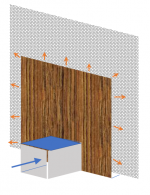
OK, the attached pic is my attempt at depicting the concept. The arrows show air flow during one part of the cycle, when the cone is moving away from the listener (listener would be off to the left and on axis with the blue arrow). The driver is hidden in this view, but is located on the panel where it meets the tunnel. The wood-grain panel is parallel to the wall (grey area) and separated from it by a few (e.g. 6) inches.
The blue arrow depicts one "source" and all the orange arrows are the other, distributed source.
The blue arrow depicts one "source" and all the orange arrows are the other, distributed source.
Attachments
Regarding the effect of the wall on the SPL of the distributed source:
The wall will double the effective source strength. However, the mouth of the tunnel protruding out from the wall will be closer to the listener. This will make that source effectively louder. I usually take the distance to the sources into account when I simulate the response of an H-frame from the nearfield measurements taken at the front and rear mouths.
For example, if the listener is 1m in front of the mouth of the tunnel, and 2m from the distributed wall sources, the +6dB gain from the wall would be counteracted by a +6dB gain from proximity to the "tunnel" source. The difference in these gains depends on the relative distances between the listener and the sources, which depends on the length of the tunnel and the size of the panel used to construct the subwoofer, and the listener position.
It surely hides the size and increases dipole separation. Eager to see how it goes. Subscribed.
The rear source is distributed around the baffle, it is energising the room at different points in space so it may thus be possible to just use global EQ at the listening position
The rear source is distributed around the baffle, it is energising the room at different points in space so it may thus be possible to just use global EQ at the listening position
Last edited:
I don't have the ability to model such a structure, however, absent a model of the acoustic output I could just build a temporary version, measure the responses at the front and rear openings, and then model the in-room response by combining those, just like what is done for a standard H-frame. Of course I could also measure the in-room response at various locations as well.
This would go in my basement man cave listening space, and the "wall" in question is made of concrete cinder block.
Thoughts? Comments? Ideas?
Go for it. Modelling bass response in a room is probably a waste of time anyway.
BTW, the chamber in front of the driver can be eliminated. It may seem like a big change but probably not, the front chamber is adding a delay much smaller than the rear so its effect is minimal hence can be removed.
No. It's not about the delay. The purpose of the front tunnel is to place that source away from the wall and closer to the listener. But moving it closer to the listener compared to the distributed source at the wall, it will be louder due to its proximity. Also, if the tunnel was removed so there was just the driver at the bottom center of a large panel, this would significantly change the axis running between front and rear sources and would place the listener closer to the null.
If I would change anything it would be to use a long U-frame with the driver at the end towards the listener, and without the panel. For a given length, a U-frame has half the bass cancellation of an H-frame. This makes it another way to reduce (by half) the length of the thing compared to a free-standing H-frame that is placed out in the room and away from the wall. It would also be a lot easier to build. But the effect of the distributed source is intriguing, so I might try both.
It's still winter here, so there is no change that I will start construction for at least another month or so. In the meantime I am thinking and planning.
Charlie, what if you built your sub right into the wall. Like infinite baffle. No cancelation and you get the benefit of two subwoofers for two rooms.")
Did you see where I mentioned that the wall is made of concrete cinderblock. It's a structural wall in the basement of my home. I am NOT going to touch it!
I have built an IB sub before (two different ones in fact) and they definitely can provide amazing bass! Unfortunately I don't currently have a place like an attic to use as the rear chamber since about 99% of my home has been made into finished space. Unless I want to install the driver in a door, which would probably need to be replaced with a solid core version and then tightly sealed, I am out of luck when it comes to an interior IB install.
But now that you brought up the topic, there is a small window up near the ceiling in that room of the basement! Hmmm, I never thought about using it for an IB sub that vents to the outside. Food for thought! But it's pretty cold here in the winter. For example it has not been above freezing during any day in the last month or so. It would have to be a "summer only" IB! But I do just happen to have a nice 15" IB driver lying around waiting to be put to use that might work perfectly.
Last edited:
Long time ago, I lived in attic, in the house I share with my kayaking buddies. Walls in attic had this leftover triangular shape empty space, which was there from the roof. There was small opening going there. Just covered with ply. I built in pa woofer cervin vega from the church organ into that cover. Thus forming IB sub. It shook the whole house. My housemates did not like it
OK, the attached pic is my attempt at depicting the concept. The arrows show air flow during one part of the cycle, when the cone is moving away from the listener (listener would be off to the left and on axis with the blue arrow). The driver is hidden in this view, but is located on the panel where it meets the tunnel. The wood-grain panel is parallel to the wall (grey area) and separated from it by a few (e.g. 6) inches.
The blue arrow depicts one "source" and all the orange arrows are the other, distributed source.
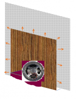
How about one big plane, with woofer in the bottom middle, back facing in the room, to allow the big open baffle be very close to the wall. Should work like a charm.
Sorry for poor rendering.
Attachments
How about one big plane, with woofer in the bottom middle, back facing in the room, to allow the big open baffle be very close to the wall. Should work like a charm.
Sorry for poor rendering.
That was already covered a few posts ago.
Is there a model to determine u-frame enclosures by driver?
Why I ask, I spoke to the AE guys and looked at 2 x 15 dipoles in a u-frame. The deal breaker was the distance from the rear wall, ~3 feet to the rear of the enclosure. I would like to test smaller AE/other subs, or move towards another approach.
Thanks, brian
Why I ask, I spoke to the AE guys and looked at 2 x 15 dipoles in a u-frame. The deal breaker was the distance from the rear wall, ~3 feet to the rear of the enclosure. I would like to test smaller AE/other subs, or move towards another approach.
Thanks, brian
- Home
- Loudspeakers
- Subwoofers
- dipole H-frame subwoofer using wall to form rear tunnel