Can somebody explain active servo speakers? Please explain like I'm a four year-old.
In context: I've had a number of Yamaha sw-P130's. As a result I have two working drivers which I intend to use for a separate project. However, I have utilised a P130 plate amp in a separate project. It is connected to random Sony driver. Does the active servo system require the technology to be present in both amp and driver?
In context: I've had a number of Yamaha sw-P130's. As a result I have two working drivers which I intend to use for a separate project. However, I have utilised a P130 plate amp in a separate project. It is connected to random Sony driver. Does the active servo system require the technology to be present in both amp and driver?
A servo measures something and corrects it using a feedback loop. It depends what is measured and corrected.
As for the Yamaha SW-P130, see Advanced Yamaha Active Servo Technology (For Sw-P130) - Yamaha NS-P110 Owner's Manual [Page 16] | ManualsLib
It appears to be an amplifier with a negative output impedance. Maybe the feedback stuff is adjusting the negative impedance in order to keep the system stable, Yamaha does not tell us about the exact meaning of 'servo'.
Last edited:
Yamaha servo was inspired by Erik Stahl's (patented) idea which consisted in electronically modifying the whole electrical circuit of a loudspeaker to change its mechanical behaviour. It seems to be the most simple and reliable way to "servo" a driver. I have 74 Mb of documentation about this kind of servoing. If you are interested, leave me a private message with an email address where I can send it.
You can esaily get a lot of documentation by searching "Erik Stahl negative impedance" :
Products & Technology - ACE-BASS
US4118600A - Loudspeaker lower bass response using negative resistance and impedance loading
- Google Patents
Products & Technology - ACE-BASS
US4118600A - Loudspeaker lower bass response using negative resistance and impedance loading
- Google Patents
A servo measures something and corrects it using a feedback loop. It depends what is measured and corrected....
It appears to be an amplifier with a negative output impedance...
"Negative output impedance" is a necessary consequence of servo feedback for conventional (AKA Rice-Kellogg) drivers and possibly all kinds of feedback and speakers.
Nothing is weirder to those familiar with audio amps than measuring output impedance and finding it is negative - as if some gremlin is curled up inside the amp and zigging when your speaker impedance zags. Weird but true.
And as far as back-EMF goes, that's exactly what you want. When the cone moves extra (AKA distortion or flopping about), the amp corrects by adding internal impedance. (Standard audio amps are designed to never change its super low output impedance ever.)
BTW, forr knows everything about that stuff.
Last edited:
Attachments

I do not know if the feedback stuff is different than having a negative output impedance. A negative output impedance could reduce linear distortion (ringing etc.).When the cone moves extra (AKA distortion or flopping about), the amp corrects by adding internal impedance. (Standard audio amps are designed to never change its super low output impedance ever.)
In order to reduce harmonic distortion, you want the opposite: a large output impedance, as can be found in articles about current drive ( = infinite output impedance).
Last edited:
You need to keep the two approaches separate.
The conventional old approach is to provide a signal to the driver (invented 100 yrs ago) the lets it work best. The behaviour of this ancient mechanism is a lot worse than any other part of the audio chain except for some of the performers. The speaker has no feedback - which is pretty negligent considering that every other part, even the performers, have feedback.A few folks advocate for a constant-current (high output impedance) amp as being better than a low output impedance drive universally used.
The feedback approach detects errors in the motion of that driver and by means of corrective feedback makes it better. It can only make it better by "tugging" at the signal "inside" the amp which makes it measure as if it had a negative resistance resistor inside.
Bet you never saw a negative resistor, eh. But when you measure the amp (sorry, can't explain that in this post), it really acts that way.
Last edited:
The main difference is that the Wheatstone Bridge motional feedback concept was developed by a fellow in a lab owned by a company big enough to send ACE-Bass into bankruptcy for patent infringement.*
Otherwise, if you're not being too OCD about the terms, pretty much the same approach to sensing back-EMF.
(This argument about ACE-Bass re-appears in this forum regularly. I wish it stop showing up. If you re-draw the bridge circuit, it looks a lot like the current circuit. BTW, I suspect the ACE-Bass current-sensing approach is the smartest-simplest way for DIYers to experiment with MFB. I started using it in 1966.)
B.
*RCA... not sure who owns the patent now
Last edited:
It seems the first who used a bridge for loudspeakers was Paul Voigt in 1924 :The main difference is that the Wheatstone Bridge motional feedback concept was developed by a fellow in a lab owned by a company big enough to send ACE-Bass into bankruptcy for patent infringement.*
A Future Without Feedback? Letters page 3 | Stereophile.com
I could not find his british patent GB231,972A .
Thanks for mentioning the Voigt Patent, I was unaware of it. (copy attached)
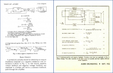
It is curious that Werner is often pointed to as the pioneer of MFB, and the bridge feedback method in particular, when many others were experimenting and discussing it in various journals in the prior decade. I guess it could be that his numerous articles in the 1957-59 timeframe (AES, JASA, IRE, Radiotronics, etc) popularized the idea and his credentials(including patent and big company backing) helped associate his name with the concept. Looking at his articles, the relevant figures and formula are no different than those in articles published before he even started working for RCA. Attached is an example(Werner 1958 IRE article on left, Clements 1952 AE on right)
It is curious that Werner is often pointed to as the pioneer of MFB, and the bridge feedback method in particular, when many others were experimenting and discussing it in various journals in the prior decade. I guess it could be that his numerous articles in the 1957-59 timeframe (AES, JASA, IRE, Radiotronics, etc) popularized the idea and his credentials(including patent and big company backing) helped associate his name with the concept. Looking at his articles, the relevant figures and formula are no different than those in articles published before he even started working for RCA. Attached is an example(Werner 1958 IRE article on left, Clements 1952 AE on right)
Attachments
Last edited:
If you built an ACE-Bass system (or properly analyze its circuit) you would find that it doesn’t behave at all like a bridge type MFB system.The main difference is that the Wheatstone Bridge motional feedback concept was developed by a fellow in a lab owned by a company big enough to send ACE-Bass into bankruptcy for patent infringement.
Here is the clearest way I know to illustrate the difference:
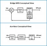
A bridge MFB system is built with 20dB or more of feedback and put in an enclosure of volume V. Use of EQ inside or outside the loop can be added to achieve a desired target response. Now, swap the enclosure for one with volume V/2, and one with volume 2*V. Measure the responses and you will find they are both nearly the same as for the original enclosure except perhaps a very small change at the bottom of the passband depending on the amount of feedback and stability margins.
An ACE-Bass system is built in an enclosure of volume V. The virtual parameters are adjusted to achieve a desired target response. As with the bridge MFB system, swap in a smaller and larger enclosure and measure the response. You will find that when put in an enclosure of volume V/2, the response does NOT stay the same. Rather, it changes to one exactly as you would expect for a woofer with physical parameters that match the virtual ones you created with the ACE-Bass system. Similarly, in an enclosure of volume 2*V, the response will change to one that you would get if a woofer with physical parameters matching the virtual parameters is used. Hopefully this also helps you understand why the ACE-Bass system can by used with any type of enclosure(vented, bandpass, transmission line, etc), not just sealed like for bridge MFB systems.
Granted, ACE-Bass can be tuned to any enclosure but at heart the error signal comes from the good old series resistor. Can't any MFB system be tuned? With all the influence of rooms, doesn't seem important to excessively fuss over the box FR.
Getting the cone (or on a good day, to get the speaker) output to resemble the input is great engineering. But I think more focus is needed on bad behaviour - which tends not to always be respected as an engineering reality. MFB of all sorts speaks to transient motion, damping, and HD.
Good to learn history of MFB.
Maybe because I am unlearned in electronics, seems there is little difference between the signal you get from a bridge versus from current feedback (AKA resistor that almost everybody uses for back-EMF signals). And after a bit of minor filtering, maybe very little difference at all. Granted, a bridge is conceptually more perfect.
Bridge is terrible in that the system ground gets screwed up - except for tube amps!!! And the bit of VC inductance it can balance out (with no small amount of analysis and figuring out what the devil is semi-inductance).
So while bridge feedback seems good in theory, not a whole lot better in practice.
Footnote: I'm always cynical when reading patent applications. My guess is that Werner's lawyers wanted him to emphasize balancing the VC inductance (which can be done with a capacitor) because the Clements diagram posted by Bolserst just has resistors in the bridge. Tiny difference, eh.
Werner's discussion in also foundational and includes, in days of tube amps, the value of positive feedback. Also his target is to model the driver in the bridge. It seems a conceptually meaningful way to look at error signals as unbalancing an otherwise well-modeled bridge. Good thing physicists in Werner's period didn't know about mysterious semi-inductance*.
*Just teasing - semi-inductance has been clarified very nicely by skilled persons on this forum.
Last edited:
Continuing to think of ACE-Bass as just a tweaked or tuned MFB system, hampers understanding of the ACE-Bass concept.Granted, ACE-Bass can be tuned to any enclosure but at heart the error signal comes from the good old series resistor. Can't any MFB system be tuned?
Reading Post #15 it should be clear that MFB systems involve error correction, but the ACE-Bass system does not.
The concept of ACE-Bass is an amplifier with unique output impedance. It is woofer and enclosure agnostic. The output impedance is the same no matter the speaker or enclosure used. Even if you replace the woofer with a resistor or short binding posts with a wire, the amplifier output impedance remains the same. The amplifier current is used in feedback loops similar to how it is used in gyrator circuits to create virtual inductors and capacitors, not as an error signal. Think of the unique output impedance as adding increments of mass, stiffness, and damping to whatever woofer is attached to the amplifier. This is similar in concept to how putting a woofer in a sealed enclosure adds an increment of stiffness to the woofer’s inherent mechanical stiffness (spider + surround).
The MFB system on the other hand, does see the bridge extracted voltage as an error signal. This signal is compared with incoming signal voltage and the difference is sent on to the power amplifier and woofer to try and minimize the error between the incoming signal and the motion of the woofer. This is why when the enclosure size is changed, the response doesn’t change much at all…the feedback loop “sees” the change as an error and drives it toward zero.
With the ACE-Bass system, changing the enclosure has no effect whatsoever on the output impedance of the amplifier.
So, the response will change just as one would expect when enclosure size is changed for a given set of woofer parameters.
As has been demonstrated for you in other threads, FR and transient motion/damping are directly linked. Fix one, you fix the other. Ignore one, you are ignoring the other. They are both manifestations of the linear response of the system. HD though, that is nonlinear response, and MFB can address it even if you modify the FR(and by association the transient response) with EQ.With all the influence of rooms, doesn't seem important to excessively fuss over the box FR… MFB of all sorts speaks to transient motion, damping, and HD.
What bad behavior do you feel is being ignored?I think more focus is needed on bad behaviour - which tends not to always be respected as an engineering reality
Attachments
Last edited:
Could be. Previous experimenters like Clements did identify the potential need to balance out the VC inductance, but only mention using an appropriately ratioed inductance to do it, not a capacitor…which is certainly a better way to do it from a $ standpoint.Footnote: I'm always cynical when reading patent applications. My guess is that Werner's lawyers wanted him to emphasize balancing the VC inductance (which can be done with a capacitor)
I agree, Werner’s analysis of the MFB circuits in use is refreshingly lucid. My point was that he didn’t come up with them on his own, rather he was analyzing methods already in use and showed how to best understand their operation and optimization. History then quickly forgot all those who came before.Werner's discussion in also foundational
My feeling is that this is a similar situation to ESLs built with LC delay lines. Everybody associates that idea with Peter Walker, because he was the one who popularized the concept, and explained it in clear conceptual terms. However, even in his AES talks he mentions that the concepts were the brainchild of others(including Kellogg of dynamic driver fame), and that all he was doing was showing a simple way to understand their operation that allowed optimization with minimal computational effort. (ie the Walker equation) Quad 63 (and later) Delay Line Inductors
Just trying to put things in historical perspective, not to detract from Werner or Walker contributions.
Werner was well aware of semi-inductance, or “impure inductance” as he called it.Good thing physicists in Werner's period didn't know about mysterious semi-inductance.
He felt it was unimportant for LF MFB circuits, which is completely understandable considering the woofers available for use at the time.
Quote from one of his many articles:
“A factor requiring especial attention is the nature of the loudspeaker’s blocked voice-coil inductance. This inductance is far from ideal in nature, being influenced by assorted hysteresis and eddy-current losses associated with the mass of iron structure surrounding it. Accurate cancelation of an impure inductance such as this may involve considerable complication of the bridge circuit. And, since the actual motion of the voice coil has little precise bearing upon the radiation of higher frequencies, accurate cancellation of the voice-coil inductance is of doubtful value.”
Bolserst - we're always in debt to you for great clarifications. But about ACE-Bass...
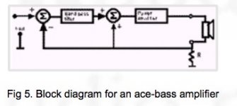
All amps have settled characteristics of their output. But ACE-Bass has resistor "R", see attachment. For perfect speakers, there's nothing of interest happening there. But where the speaker is being naughty, provided a trail is encoded into the back-EMF, that's an error signal. The ACE-Bass amp uses that feedback correctively like all other VC-bound MFB systems, bridge or current resistor.
Bad behaviour includes HD, as you mention, but also shortcomings in playing transients, continuing to rumble-on at the off-set of a note, etc. Granted, you can make a good guess at errors in the speaker's output by Klippelizing it. But that just shows the naughtiness isn't mysteriousness; which is comforting if you can fix the problems. Funny, I just take for granted that crude devices like the Rice-Kellogg driver which tries to pulsate the air with a hunk of cardboard and copper will always need feedback to fix bad behaviour.
Nice to hear such praise for Werner whose later exploits in audio seem hard to find. I wonder if Olson, the great man at RCA labs, may have been his mentor? Or why General Sarnoff terminated the Camden or Princeton labs? Or the loss to HiFi?
Attachments
Last edited:
- Home
- Loudspeakers
- Subwoofers
- Active Servo Subwoofers