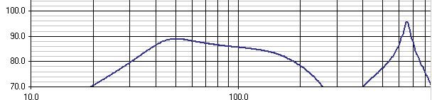
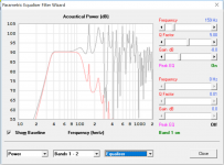
I'm designing a small 3 liter closed + .7 liter vented bandpass near field sub 6" cylinder woofer, if you can call F3 at 39 a sub woofer. I have the upper F3 and lower F3 where I want them to interface with my midrange but I see a nasty peak in the simulation model (see picture.) Is that going to be a problem? I assume it is an acoustical problem that can't be fixed with a 220 xover point. The model in the picture already has heavy stuffing in the vented .7 liter section but maybe some different type if stuffing will minimize the peak.
Any ideas or is this not a problem?
Thanks
Any ideas or is this not a problem?
Thanks
Attachments
It is an acoustical problem, yes.
However, it'll only be an issue if the woofer excites that resonance, by producing some 650Hz content. That can be in the form of harmonic distortion from driving it hard, or if you feed full-range signal into the sub, that peak will be quite obvious.
A reasonably steep crossover should fix it. If it doesn't, a carefully aimed notch filter will.
FWIW, I had an old 6th order bandpass cabinet in my PA system for a while. Sounded pretty good, but there was a big peak at 340Hz, which happened to correspond to the internal (square) dimensions, leading to a big standing wave. It sounded much better once I'd measured and got the notch in place.
Chris
That sounds reasonable - notch filter - the peak is 620 and at 540 and 700 it is down 12db. To bring the range down about 10db from the average 90db value, it needs to be down 12 db at 540 and 700. It is an 8 0hm speaker with a Re of 5.6. I tried to plug those numbers into a notch filter calc but it seem to lower HZ on either side of 620 a lot, ie down 6 at 300 and 1000 which is unacceptable. Is a notch filter going to work?
thanks
thanks
That would be nice - a line level notch would be perfect - Is it possible to use only resistors and capacitors so we could make a variable hz peak and variable bandwidth with pots? Has anyone done that?
No crossover, since I'm bi-amping it with a BSC on the FE83 3" in a globe enclosure that has Led color lights in it.
Those charts are based on using the UniBox simulator (based on volume and doesn't ask if it is a pipe or not) which seems to indicate that 39 hz is possible with Peerless 830855 4" SDS (remember near field so SPL is not as important) with the .7 liter vent box tuned to 80 hz (1 inch x 10") port.
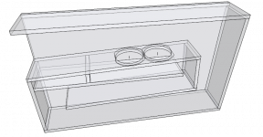
I'm using it in a 6" PVC pipe with an adjustable speaker baffle so I can vary the ratio of the closed vs vented chambers while a sine wave is playing. That would be the reason for a variable notch filter as that peak will move. Or is that peak going to be a problem that I will be able to hear in post 1?
No crossover, since I'm bi-amping it with a BSC on the FE83 3" in a globe enclosure that has Led color lights in it.
Those charts are based on using the UniBox simulator (based on volume and doesn't ask if it is a pipe or not) which seems to indicate that 39 hz is possible with Peerless 830855 4" SDS (remember near field so SPL is not as important) with the .7 liter vent box tuned to 80 hz (1 inch x 10") port.
I'm using it in a 6" PVC pipe with an adjustable speaker baffle so I can vary the ratio of the closed vs vented chambers while a sine wave is playing. That would be the reason for a variable notch filter as that peak will move. Or is that peak going to be a problem that I will be able to hear in post 1?
Those charts are based on using the UniBox simulator (based on volume and doesn't ask if it is a pipe or not) which seems to indicate that 39 hz is possible with Peerless 830855 4" SDS
It's a neat little woofer
")
Attachments
That sounds reasonable - notch filter - the peak is 620 and at 540 and 700 it is down 12db. To bring the range down about 10db from the average 90db value, it needs to be down 12 db at 540 and 700. It is an 8 0hm speaker with a Re of 5.6. I tried to plug those numbers into a notch filter calc but it seem to lower HZ on either side of 620 a lot, ie down 6 at 300 and 1000 which is unacceptable. Is a notch filter going to work?
thanks
If the impedance is fairly steady around 5 or 6 ohms in the 540-700 region, a parallel notch can be fairly effective. Check the impedance as is if you have a way to verify it.
For a parallel notch, R L and C components are in parallel with each other, and the RLC network is in series with the driver. A good starting point would be R = 25 ohms, L = 2.0 mH, C = 33 uF. The L and C values center the notch at 620 hz, and the R value brings 540 and 700 down 12 dB for a 5 to 6 ohm impedance in that area.
Another option would be to make a very steep low pass roll off above the usable frequency, which will push the 620 hz peak down, along with everything to the right. If the impedance is not constant (i.e. wild fluctuations), a low pass filter could be a better solution.
Thanks Dave,
Those figures are very helpful. I could not find a notch filter calculator that shows the minus DB at 540/700. Which one did you use?
Let's assume I could use a filter before the amp (line in.) Would it be easier to have a variable low pass filter or a notch filter since I will be varying the volume in the chambers? If so, is there a circuit out there that can vary where the hz peak is, the minus db level needed and can vary the two "end" hz?
Thanks
Thanks Dave,
Those figures are very helpful. I could not find a notch filter calculator that shows the minus DB at 540/700. Which one did you use?
Let's assume I could use a filter before the amp (line in.) Would it be easier to have a variable low pass filter or a notch filter since I will be varying the volume in the chambers? If so, is there a circuit out there that can vary where the hz peak is, the minus db level needed and can vary the two "end" hz?
Thanks
I wrote a program in Mathcad for the notch.
I have a pair of tapped horn subs that are powered with their own plate amps. With driver in enclosure, there were 12-15 dB SPL peaks (several) just above the usable region. The impedance also had 3 nasty peaks. The plate amp has variable xo frequency, variable phase, and of course gain, but not enough adjustment to get rid of that stuff. I ended up getting a miniDSP to roll it off at 48 dB/octave just above the nice flat plateau. It took a few trials to find the right cutoff frequency, but finally found it. The miniDSP is placed between the source (cd player) and the plate amp. With the right adjustments, they blend in quite well with my bookshelf speakers. This was my only adventure with line-level.
You could find an on-line xo calculator and check out what it might take for 2nd, 3rd, and 4th order low pass. Since your peak at 620 is far enough away from the usable region, you might be able to roll off that unwanted peak with only 2nd order. Much easier than a notch.
Last edited:
The way to completely eliminate any and all port resonances like these from a bandpass type enclosure is to use a passive radiator instead of a port.
The next option is to think about how you can deal with this resonance, how obvious the resonance will be, etc. The plot shows a peak around 650 Hz that is about +6dB from the middle of the passband SPL. This self-resonance at 650 Hz is excited by the "white noise" of the air rushing in and out of the port. Even another driver (like a midrange) that is producing a 650 Hz tone nearby could excite the port's self resonance. Any energy at 650Hz reaching the port will do it. One way to deal with this inevitability is to try to eliminate any 650Hz energy. One approach would be to build the bandpass enclosure with the port firing down and out the bottom, and then put something like 1-2 inches of foam, a rug with a thick pile, or other material that will adsorb strongly at 650Hz. Make sure to leave at least 1.5 time the port diameter between the port exit and any material below. You could even go as far as building a tuned adsorber like a Helmholtz resonator right there. Built this way, only the moving air in the port will cause a resonance, but most of that will be eliminated before it propagates away into the room.
There are other approaches, like changing the bandpass design so that port aspect ratio is not so high (aspect ratio is length/width). High aspect ratio ducts self-resonate strongly, while low aspect ratio ducts do not. If the volumes of the BP enclosure compartments are made larger you should be able to make the port shorter for the same tuning frequency. This will push the resonance frequency higher and reduce the Q.
It is important to understand that the resonance is NOT due to electronic input to the driver but due to the movement of air in and out of the port at low frequencies. Thus, adding a notch filter on the woofer/subwoofer driver in the BP enclosure will do nothing to reduce or eliminate the resonance.
Last edited:
One other way is to add a resonator "stub" that's tuned to 650 Hz to the vent itself. I personally haven't tried this, but there is a thread across on the PE site somewhere where someone demonstrated how this was done for a small vented speaker with a long vent - he used a stub to tame the out of band resonance caused by the vent.
Right, band-stop filter [helmholtz resonator] like DSL used on the DTS20: http://users.cms.caltech.edu/~ps/All.pdf
GM
GM
So Dan, do you hear those peaks in your T-Line and if not, is it because it is a T-Line?
I've not built this one, it's an idea from long ago.
I've built others and the answer is no, not when used with a reasonable filter. Our simulations are mathematical models and the resonances are a bit exaggerated when compared to real life.
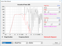
Standard LFE preamp outputs are 24 dB per octave LPF, see the attached examples of filter and EQ if you have the inclination.
Attachments
One other way is to add a resonator "stub" that's tuned to 650 Hz to the vent itself. I personally haven't tried this, but there is a thread across on the PE site somewhere where someone demonstrated how this was done for a small vented speaker with a long vent - he used a stub to tame the out of band resonance caused by the vent.
I have read that this is often used in automobile exhaust systems to quiet pipe resonances. I think this is one of the arguments for putting a driver 1/3 of the way along a closed pipe horn, or something like that. I'm a little fuzzy on the exact recollection.
It is important to understand that the resonance is NOT due to electronic input to the driver but due to the movement of air in and out of the port at low frequencies. Thus, adding a notch filter on the woofer/subwoofer driver in the BP enclosure will do nothing to reduce or eliminate the resonance.
Little or no experience with bandpass enclosures here, so trying to understand. Is the 650 hz peak generated primarily from a different, lower frequency in the desired bandpass region (like a multiple of a number)? Still it seems to me that the movement in the port requires a driving force at the resonant frequency. By greatly reducing the power provided to the driver at that frequency, wouldn't that affect the spl peak to some noticeable level?
Brian, GM,
The helmholz resonator sounds like an efficient solution. Thanks for the info.
You guys are great - thanks - I started a tread about a month ago about a Bose patent design that had chambers off of a quarterwave box of theirs and it has come full circle. I was asking about what those chambers were for and, voila you guys have the answers. Also, thanks for that PDF since that goes into detail about that Bose patent.
I think what I will do is to use a PEQ like Peace.exe though my windows tablet or laptop which has a shelf filter, I think 48db, around 200 hz and that should take care of it. By the way, if you haven't seen the power of that software, you should give it a try: 7.1 with each channel having its own EQ and many more features.
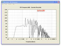
NeoDan, what program did you use to get those graphs?
I think what I will do is to use a PEQ like Peace.exe though my windows tablet or laptop which has a shelf filter, I think 48db, around 200 hz and that should take care of it. By the way, if you haven't seen the power of that software, you should give it a try: 7.1 with each channel having its own EQ and many more features.
NeoDan, what program did you use to get those graphs?
- Status
- This old topic is closed. If you want to reopen this topic, contact a moderator using the "Report Post" button.
- Home
- Loudspeakers
- Subwoofers
- bandpass port resonance elimination