Hi xrk971,
Your AkAbak script uses 'closed' Enclosure elements to describe the two chambers, and then specifies those chambers as stand-alone cavities rather than having actual chambers connected in-line with the vent Duct elements. As can be seen from the attachment, this means that sound energy from the rear side of the driver diaphragm is allowed to arrive at vent 1 without passing through chamber 1, which would not be the case in a practical system. I cannot see how our topologies can be equivalent.
The section titled "Modeling enclosed acoustics" starting on page 64 of the AkAbak Main Manual describes how to model a multi-chamber band pass enclosure.
Kind regards,
David
David,
I think what you are saying is that a rear or front chamber with a vent can be modeled more accurately with a series of ducts that form a chamber and having a driver located at the node between two ducts forming a chamber. You could take it another step and add a third duct and put the vent at the interface of the 2nd and third duct. But if one makes the assumption that the chamber is small relative to wavelengths of importance (such as bass lengths) then the chamber can be assumed to be homogeneous and a single node is sufficient. I have modeled bass chambers this way literally thousands of times and it is quite accurate when compared to built speakers. When chambers are large relative to the frequencies you are interested in, then it makes sense to break it up like the multichamber example on p64. For example, on the model of the Karlson speaker, the rear and front chambers are broken up into about 9 total ducts. Actually, not even ducts, but "Waveguide" elements because the cross sectional areas are not constant. If you go to Net/Acoustic/Enclosure you will see a dialog that forms the enclosure or single node element. It has options for a vent, the example below is such a single node bass reflex chamber where the vent CSA and chamber frequency is defined.
Code:
System 'Bass Reflex'

Def_Driver 'RS225-8'  |Dayton Ref Series 8in 8ohm, 0.38 Qts, 7 mm xmax, 88.8 dB
 Sd=214cm2
 Bl=9.05Tm
 Qms=1.46
 Qes=0.51
 Mms=35.8g
 fs=28Hz
 Vas=56.8L
 Le=0.86mH
 Re=6.53ohm

Driver Def='RS225-8' 'Driver 1'
Node=1=0=10=11

Radiator 'Direct_Rad' Def='Driver 1'
Node=10

Enclosure    'Bass chamber'  Node=11
    Vb=24L  Qb/fo=0.1  Lb=4in  QD/fo=1
    fb=42Hz  dD=2.5in

OFF
Duct    'Vent'  Node=11=12
    dD=2.5in  Len=8in  QD/fo=1

OFF
Radiator 'Vent_Rad' Def='Vent'
Node=12
One can do the same this with a separate "Duct" for the vent, still using the same chamber by switching the duct and duct rad on and commenting out the resonant freq of the enclosure:
Code:
System 'Bass Reflex'

Def_Driver 'RS225-8'  |Dayton Ref Series 8in 8ohm, 0.38 Qts, 7 mm xmax, 88.8 dB
 Sd=214cm2
 Bl=9.05Tm
 Qms=1.46
 Qes=0.51
 Mms=35.8g
 fs=28Hz
 Vas=56.8L
 Le=0.86mH
 Re=6.53ohm

Driver Def='RS225-8' 'Driver 1'
Node=1=0=10=11

Radiator 'Direct_Rad' Def='Driver 1'
Node=10

Enclosure    'Bass chamber'  Node=11
    Vb=24L  Qb/fo=0.1  Lb=4in  QD/fo=1
|    fb=42Hz  dD=2.5in

|OFF
Duct    'Vent'  Node=11=12
    dD=2.5in  Len=8in  QD/fo=1

|OFF
Radiator 'Vent_Rad' Def='Vent'
Node=12
Now I can break up the rear chamber into three sections using 3 ducts each equivalent in volume and put the driver between the first two and the vent between the 2nd and 3rd:
Code:
System 'Bass Reflex 3'

Def_Driver 'RS225-8'  |Dayton Ref Series 8in 8ohm, 0.38 Qts, 7 mm xmax, 88.8 dB
 Sd=214cm2
 Bl=9.05Tm
 Qms=1.46
 Qes=0.51
 Mms=35.8g
 fs=28Hz
 Vas=56.8L
 Le=0.86mH
 Re=6.53ohm

Driver Def='RS225-8' 'Driver 1'  | driver connected to node 101 between ch1 and ch2
Node=1=0=10=101

Radiator 'Direct_Rad' Def='Driver 1'
Node=10

| *** Chamber segment 1
Duct    'Ch1'  Node=100=101
    dD=2.5in  Len=8in  QD/fo=1
    WD=12in  HD=10in  Len=4.07in  QD/fo=1


|Chamber segment 2
Duct    'Ch2'  Node=101=102
    dD=2.5in  Len=8in  QD/fo=1
    WD=12in  HD=10in  Len=4.07in  QD/fo=1

|Chamber segment 3
Duct    'Ch3'  Node=102=103
    dD=2.5in  Len=8in  QD/fo=1
    WD=12in  HD=10in  Len=4.07in  QD/fo=1

| *** vent connected to node 102 between ch2 and ch3
Duct    'Vent'  Node=102=12
    dD=2.5in  Len=8in  QD/fo=1

|OFF
Radiator 'Vent_Rad' Def='Vent'
Node=12
If you run these 3 scripts you will see they produce about the same result for 1kHz and below.
Similarly, for a 6th order bandpass, you can add all the extra nodes using multi-segment ducts, but it makes little difference for low frequencies and small length chamberrs.
However, for a front chamber where the exit aperture is far from the inter chamber vent, it does make a difference to use the appropriate multi-chamber duct topology for the front chamber. The rear chamber can still be single node.
Hope this helps.
I have modeled bass chambers this way literally thousands of times and it is quite accurate when compared to built speakers.
Since you have done this thousands of times, could you please post one or two sims compared to your built speaker traces (particularly in real rooms assessed from the listening position not near-field, if at all possible) so we can celebrate seeing them as "quite accurate". Or even just a link to where we can see a gallery of these.
Being in research for decades, I really like to see data and think that's good practice on the web.
Thanks.
Ben
Last edited:
I don't model the room from listening position. I model either near field or anechoic conditions. The one speaker I designed that was measured properly in a nearly reflection free environment outdoors matched to a T but unfortunately cannot share that as it is under wraps for IP. I don't have a gallery, but all you have to do is search for any of my projects to see that they typically have: model, measurement, and sound clips. The closest one relevant to this thread is the 6th order series band pass thread called "Light as Air sub..."
Hope this helps.
Hi xrk971,
It does, greatly. Thank you.
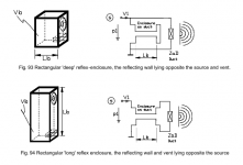
I think I now better understand what is going on here. The clue is given on page 171 of the AkAbak Main Manual, where the distinction is drawn between a rectangular 'deep' reflex enclosure having the reflecting wall lying opposite the source and vent (Fig 93), and a rectangular 'long' reflex enclosure having the reflecting wall and vent lying opposite the source (Fig 94). In your model you assume a deep enclosure, whereas coming from an axisymmetric horn loudspeaker perspective, I automatically assume a long enclosure
.Mystery solved. Thanks again - this has been a most interesting exercise!
Kind regards,
David
Attachments
Last edited:
I guess near-field will have to do even though there's still quite a leap to room behaviour.
"Light as air" returned 1460 hits at DIYaudio. Can you be more specific please.
Thanks.
Ben
You might also like this thread:
http://www.diyaudio.com/forums/subwoofers/264737-pp-slot-loaded-sub-alpine-swr-12d2.html
Lot's of help from Tb46 on CAD and Lawbiding on construction there.
- Status
- This old topic is closed. If you want to reopen this topic, contact a moderator using the "Report Post" button.
- Home
- Loudspeakers
- Subwoofers
- Bandpass enclosure - independent front chamber tuning?