Hi,
See below for where Lewin disingenuously nicked his quote from.
I guess those in Lewin's field don't read thermodynamics papers.
rgds, sreten.
Shame on me, sreten. I, being a physicist myself, always believed it was Boltzmann's quote till someone "corrected" me yesterday and "Googled" it again and when more of the top research results pointed to Lewin I was suitably deceived. Thanks for assuring me I was right 😱 (and for your inputs of course).
Qt=0.7 doesn't have the best transient response, 0.5 does same as a sealed alignment...
GM
Thanks for your inputs GM. I am missing something in the above piece though, as Vance's book says S=0.7 has the best transient performance which is degraded with S=0.5, which had me believe S=0.5 cannot equate to a sealed box. What did I miss?
I will state the motivation for my original question about BPs. My original idea was in fact to start with a sealed alignment, and use an independently tuned front chamber "add on" to introduce an acoustic rolloff that would supplement a crossover, thereby allowing for a lower order passive crossover. So in terms of this specific objective, one could say that shifting to a horn alignment would entail a change of track altogether, rather than allowing me to tweak/"add on" to a sealed chamber. Would the "add on" idea therefore qualify as stupid?
It is quite easy to model this and try adjusting the front/rear chambers and vent dia x lengths to optimize what you are looking for. 30Hz to 300Hz is kind of large - probably beyond the capability of a band pass box.
Thanks xrk971, never used Akabak, time to try it out now! I do have LEAP V so I could indeed model a BP in LEAP without asking my question, but as I mentioned I did not want to get into a simulation without knowing if there is a theoretical foundation or acceptability for what I set out to simulate.
I did not want to get into a simulation without knowing if there is a theoretical foundation or acceptability for what I set out to simulate.
Despite my earlier misgivings and recognizing the obstacles which persons engaged in theory face when in a new area of study, I see you are asking some pertinent questions.
Your purpose is to produce to good sound. Simulations - as slavishly adhering to Thiele's approach - are electric analogies to acoustic parameters; but are generally accepted as reliable even if rather more "reduced" (simplified) than adherents understand.
The leap occurs when taking the bare-bones output variables of a simulation and supposing it encompasses the whole of your home psycho-acoustic experience. "Solving" for freq response and Q are not the whole story.... even supposing you had a good notion of what output values were desirable.
Let me ask you this question: what is the proper Q for a loudspeaker reproducing a recording of a cello?
Ben
Last edited:
Let me ask you this question: what is the proper Q for a loudspeaker reproducing a recording of a cello?
Ideally, the speaker should be the same as a cello body - a multimode vibrating 3d panel much like a distributed mode loud speaker which has many different resonant peaks and many different Q's. I think the ideal speaker for a cello, is a cello fitted with an electro-acoustic transducer or 'exciter' right under the bridge or above the internal sound bar. That way, you have a vibrating element with the perfect superposition of vibrational modes and Q's that, in their sum, make up the sound we hear as a cello.
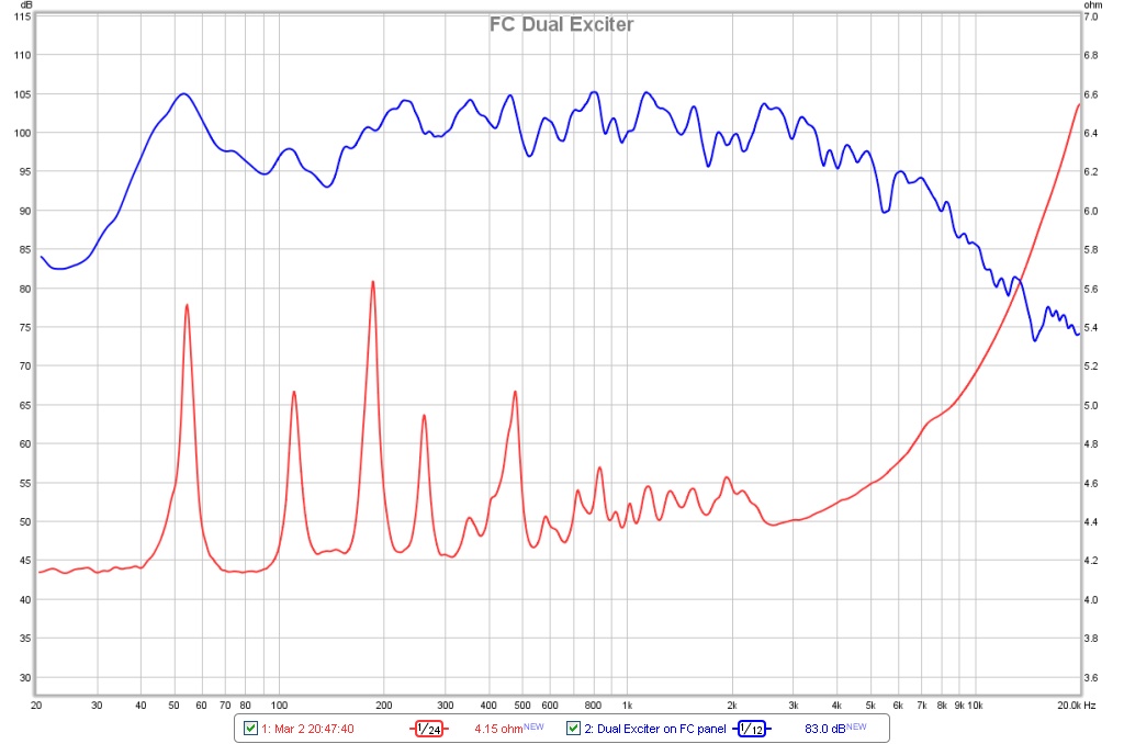
Here is a vibrating panel DML that I made, and its measured SPL and impedance peaks. I would imagine a cello to look kind of like this but even more complex. What is the 'Q' of this DML? No single value can describe...
Last edited:
It is quite easy to model this and try adjusting the front/rear chambers and vent dia x lengths to optimize what you are looking for. 30Hz to 300Hz is kind of large - probably beyond the capability of a band pass box. Here is a sample script for a 6th order series band pass. It is simple and possible with 9 lines of code. Very powerful and very easy to use once you have sample scripts to work with.
Hi xrk971,
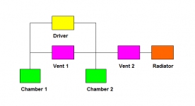
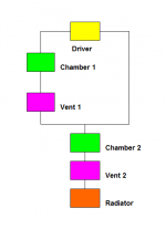
You have modelled the 6th order series band pass enclosure as shown in Attachment 1. Shouldn't it be modelled as shown in Attachment 2?
Kind regards,
David
Attachments
Ideally, the speaker should be the same as a cello body - a multimode vibrating 3d panel much like a distributed mode loud speaker which has many different resonant peaks and many different Q's. I think the ideal speaker for a cello,
Ummm, wouldn't that sound like two cellos?
B.
Despite my earlier misgivings and recognizing the obstacles which persons engaged in theory face when in a new area of study, I see you are asking some pertinent questions.
Your purpose is to produce to good sound. Simulations - as slavishly adhering to Thiele's approach - are electric analogies to acoustic parameters; but are generally accepted as reliable even if rather more "reduced" (simplified) than adherents understand.
The leap occurs when taking the bare-bones output variables of a simulation and supposing it encompasses the whole of your home psycho-acoustic experience. "Solving" for freq response and Q are not the whole story.... even supposing you had a good notion of what output values were desirable.
Let me ask you this question: what is the proper Q for a loudspeaker reproducing a recording of a cello?
Ben
1. I was not after a "simplistic" model such as one perhaps "slavishly adhering to Thiele's"
2. I was not supposing that a bare-bones output of a simulation model encompasses etc etc.
3. I am not attempting to get to "perfect" models that would, e.g., answer for what Q is appropriate in a specific complex situation.
4. Vented enclosures with arbitrary trial-and-error alignments got a bad name in the early days till we had a methodology that established that not all vented alignments make sense. All I want to know is whether there exists a methodology/alignments for wide-BP enclosures or whether that is an oxymoron, irrespective of how "perfect" such methodology is.
5. The spirit is more or less that of a Physicist modeling the real world: you know that Newton's model as well as Einstein's are approximations of the real world. Neither is perfect, which means you neither embrace either without question nor do you reject both knowing neither will model all of the known universe. Furthermore, in a given situation you first want to know whether there is at all a way to arrive at a workable 101 model before you refine it, irrespective of how good or bad that model will be.
Looks like I am still trying to define my question at post #28 🙂.
Last edited:
For sealed box, Qtc between 0.5 and 0.7. Not only for cello, but for every imaginable instrument. But that is only one part of the whole story - if low frequency cut-off F3 is too high, than it can't reproduce accurately cello, tuba, double bass, ...Let me ask you this question: what is the proper Q for a loudspeaker reproducing a recording of a cello?
No, the ideal loudspeaker for the cello (and for any other instrument) is a conventional loudspeaker with flat frequency response and a non-resonant body (box).Ideally, the speaker should be the same as a cello body - a multimode vibrating 3d panel much like a distributed mode loud speaker which has many different resonant peaks and many different Q's. I think the ideal speaker for a cello, is a cello fitted with an electro-acoustic transducer or 'exciter' right under the bridge or above the internal sound bar.
Last edited:
Vented enclosures with arbitrary trial-and-error alignments got a bad name in the early days till we had a methodology that established that not all vented alignments make sense.
snip
Looks like I am still trying to define my question at post #28 🙂.
The model of electrical analogies to Helmholtz resonators goes back a long way. I think Beranek popularized it 70 yrs ago and maybe Olson before that. Not exactly "yesterday" as your words suggest. Surely you've educated yourself in the background to this model you rely on? Otherwise, you wouldn't compare it to Newton and Einstein.
You wrote, "make sense". Make sense how? Make sense who? What did you mean by that?
Anybody who knows the distinction between theoretical physicists and experimental physicists will see what this debate is really about. Voltaire's Candide, as I said earlier.
Was it George Gamow who said physics doesn't predict when you'll have a flat tire on your car?
Ben
I really like the sound of a leaky sealed box. I wonder how you'd model that?
Last edited:
Thanks for your inputs GM. I am missing something in the above piece though, as Vance's book says S=0.7 has the best transient performance which is degraded with S=0.5, which had me believe S=0.5 cannot equate to a sealed box. What did I miss?
I will state the motivation for my original question about BPs. My original idea was in fact to start with a sealed alignment, and use an independently tuned front chamber "add on" to introduce an acoustic rolloff that would supplement a crossover, thereby allowing for a lower order passive crossover. So in terms of this specific objective, one could say that shifting to a horn alignment would entail a change of track altogether, rather than allowing me to tweak/"add on" to a sealed chamber. Would the "add on" idea therefore qualify as stupid?
You’re welcome!
I haven’t read his LDC, but I’m assuming that he’s referring to a 0.707 Qtc max flat T/S sealed alignment, which has a 2nd order roll-off [12 dB/octave], so for transient ‘perfect’ it needs to be a 1st order [6 dB/octave] roll-off = 0.5 Qtc, ergo only ‘degraded’ due to having a much higher F3.
As such, you can add a front chamber to get a ‘quicker’ [higher Qt] HF roll-off, but short of a compression horn you’re still going to be band-width [BW] limited to a T/S upper mass corner = [2*Fs/Qts] and the much larger cab, higher F3 of a 0.5 Qtc sealed alignment.
From this we see that the BW can be increased to a practical limit based on how low both the Fs and Qts is with the understanding that the lowest F3 can only be with a 0.707 Qts, ergo merely what most HI-FI folks find an acceptable transient response. Frankly, based on the world’s largest consumer speaker manufacturer’s products, up to a ~1.4 Qts is acceptable.
If you’re referring to the roll-off of the front chamber, then AFAIK the only thing you can do is make it under-damped [too big] and maybe add stuffing as required to get the desired 1st order roll-off. Don’t recall ever experimenting with this except with truncated horns, but a sim seems to support it’s doable.
Regardless, whether it’s ‘stupid’ or not to go this route is up to you depending on your performance goals. If it doesn’t, then some form of compression horn will be required AFAIK.
GM
GM has - again - provided a smart application of the model and even gone beyond that to practical implications for DrRam. But even more than that, GM has gone full-circle and, if I read him correctly, is implicitly questioning the assumptions of DrRam.
While DrRam runs full-speed-ahead with his choice of enclosure, I really wonder if he has any good basis in psycho-acoustic evidence for his unyielding theoretical assumption that minimum phase shift is a goal worth fussing about (esp. when you end up with non-feasible designs, as GM has capably shown).*
Ben
*me and a lot of other folks with DSP crossovers have good audible reasons for liking our BUT24 and BUT48 crossovers... esp if you own a pencil and the backside of an old envelope and are capable of estimating the excessive input to your mid-range driver at 50 Hz when powered-away at 6dB/8ave by your crossover. I wonder if DrRam is familiar with Doppler Shift in loudspeakers???? Or is that a theory too far?
Last edited:
Hi,
I'll just point out that a 30Hz to 300Hz bandpass causes
more problems that if fixes and a waste of the front volume.
They are very parameter finicky and can't be designed on paper.
Bandpasses big advantage is output at front port resonance,
but by the time you get to 300Hz any bass driver will have
loads of output capability negating its main advantage.
4th and 6th order bandpasses make most sense with
lower front tunings, but I don't like them at all for
real diy hifi purposes except for some minor cases.
rgds, sreten.
Hi xrk971,
You have modelled the 6th order series band pass enclosure as shown in Attachment 1. Shouldn't it be modelled as shown in Attachment 2?
Kind regards,
David
Chambers in Akabak have only one node - that is no distinction of inlet outlet. The diagrams you have drawn are topologically equivalent of the chamber element is used.
I come up with the attached arrangement, the driver is only connected (coupled) to the vents through the chambers.
Hi Oliver,
The chambers and vents shown in my second equivalent circuit diagram are assumed to be AkAbak duct elements. By definition, a duct element has a single input and a single output. The arrangement shown in your diagram has two separate inputs into chamber 2 (outputs from driver and vent 1).
This is why my diagram is slightly different to yours 🙂.
Kind regards,
David
Chambers in Akabak have only one node - that is no distinction of inlet outlet. The diagrams you have drawn are topologically equivalent of the chamber element is used.
Hi xrk971,
Your AkAbak script uses 'closed' Enclosure elements to describe the two chambers, and then specifies those chambers as stand-alone cavities rather than having actual chambers connected in-line with the vent Duct elements. As can be seen from the attachment, this means that sound energy from the rear side of the driver diaphragm is allowed to arrive at vent 1 without passing through chamber 1, which would not be the case in a practical system. I cannot see how our topologies can be equivalent 🙂.
The section titled "Modeling enclosed acoustics" starting on page 64 of the AkAbak Main Manual describes how to model a multi-chamber band pass enclosure.
Kind regards,
David
Attachments

I'll just point out that a 30Hz to 300Hz bandpass causes more problems that if fixes and a waste of the front volume. They are very parameter finicky and can't be designed on paper.
Bandpasses big advantage is output at front port resonance, but by the time you get to 300Hz any bass driver will have loads of output capability negating its main advantage.
4th and 6th order bandpasses make most sense with lower front tunings, but I don't like them at all for real diy hifi purposes except for some minor cases.
rgds, sreten.
Thanks sreten, for sticking to my question and for providing that brief but precise perspective - pretty much the kind I was looking for. No gain without pain; it was certainly worth going through some off-topic comments and sarcasm in the process 😀...all in good spirit. I bring my responses to a close here but I will continue to monitor the thread for more useful and helpful responses.
Once again thanks to the many members who provided constructive and helpful comments.
Best - Ram
- Status
- Not open for further replies.
- Home
- Loudspeakers
- Subwoofers
- Bandpass enclosure - independent front chamber tuning?