This topic started originally in the Hornresp thread here: http://www.diyaudio.com/forums/subwoofers/119854-hornresp-464.html#post3979664 and interest in it continues. Being OT from David McBean's excellent thread devoted to Hornresp, I am creating a new thread here to fully discuss this topic.
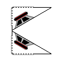
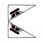
Legis asked if a very simple V-horn with dual drivers and an open back could be simulated in Hornresp. The sketch provided by Legis looked like this:
I proceeded to model it using Akabak. It is quite simple to model as a 2-segment linear horn with the backs of the drivers acting as open faced radiators. The drivers are Eminence Deltalite II 15 inchers. The script is here:
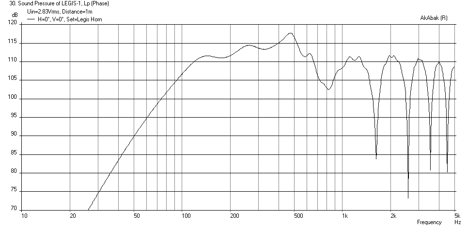
This code produced a response which looks like this (no wall effects with horn on floor in 2 pi space):
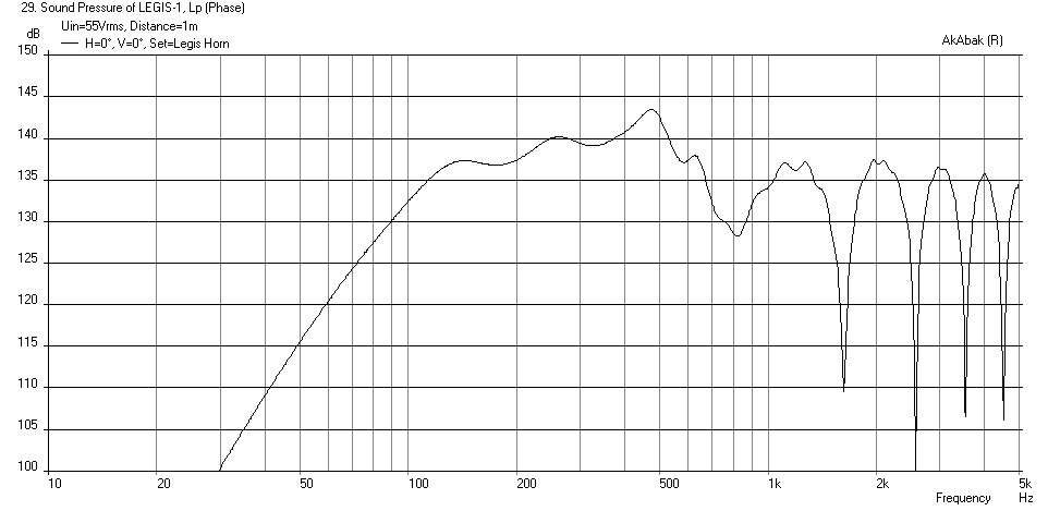
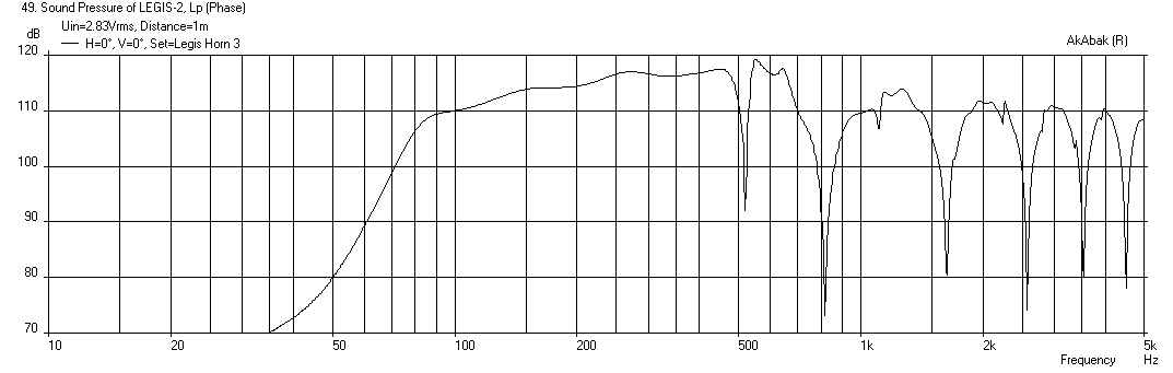
The corresponding SPL at xmax of 4.8mm and 55v (with high pass filter at 75 Hz) is quite impressive:
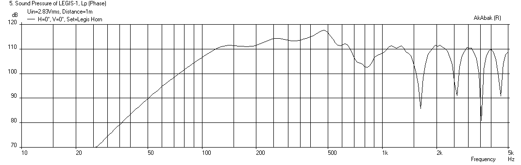
If you place the horn 2 m in front of a back wall, the wall reflections make the output at 0deg in front look like this:
Legis then asked if either a sealed chamber behind the drivers could be added, say 30 liters, or maybe a leaky box with a resistive vent to produce a cardioid response. I proceeded to model that and produced the following results:
Case (a) open back:
Case (b) sealed 30 liter back chamber with Q=0.5:

Case (c) 30 liter back chamber with 4 in dia x 10 in long vent:
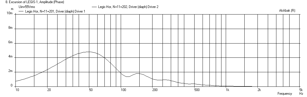
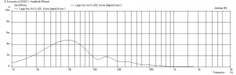
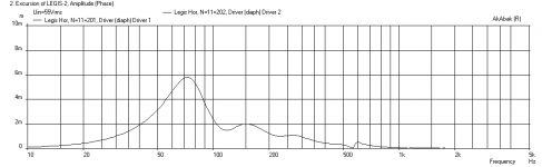
What I noticed that was interesting was that the open back case actually loads the cone better than the sealed back chamber, as can be seen from the cone excursion plots of each case at 55 volts (the drive voltage needed to hit xmax for the open back case):
Case (a) cone excursion for open back:
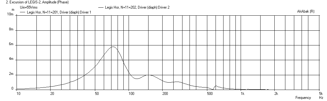
Case (b) cone excursion for sealed back (30 liters):
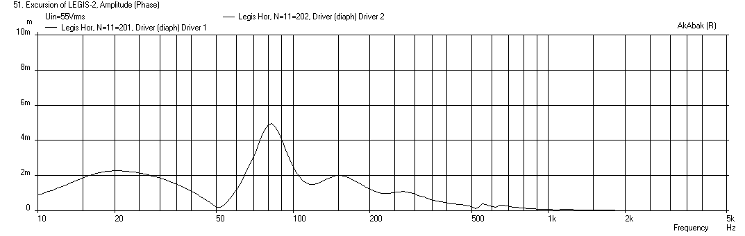
Case (c) cone excursion for 30 liter chamber with 4 in dia x 10 in long vent:
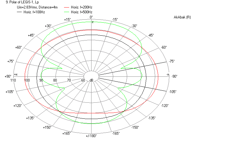
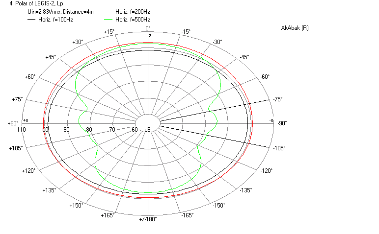
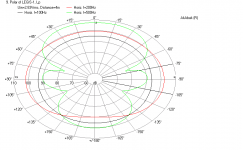
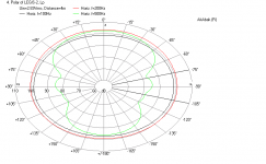
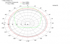
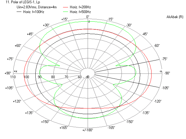
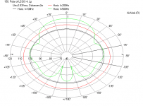
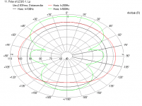
Here are the polar responses for 100 Hz, 200 Hz, and 500 Hz at 4 meters away for the above cases:
Open back polar:
Sealed 30 liter chamber closed back polar:

Vented back polar:
I am now working on the effects of a resistive vent back similar to the one posed by Legis as illustrated here:
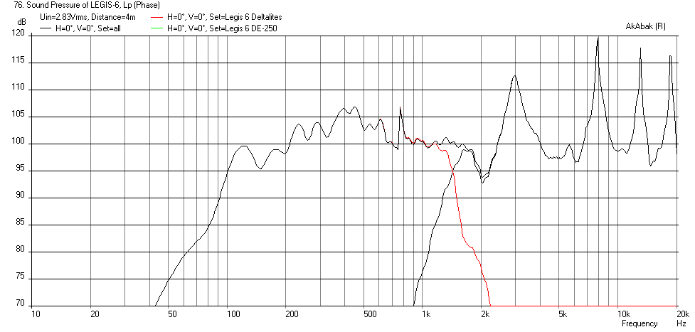
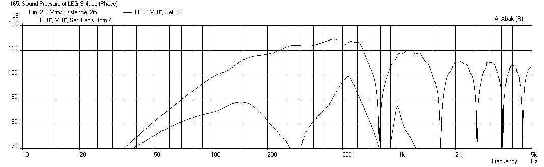
If you "Synergize" this with a compression chamber and injection port for each driver (still open back) and the addition of a B&C DE-250 CD XO at 1600Hz at the vertex you get this:
More info in post #156: http://www.diyaudio.com/forums/subwoofers/258706-study-dipole-cardioid-bass-horn-16.html#post3999668
Legis asked if a very simple V-horn with dual drivers and an open back could be simulated in Hornresp. The sketch provided by Legis looked like this:
An externally hosted image should be here but it was not working when we last tested it.
I proceeded to model it using Akabak. It is quite simple to model as a 2-segment linear horn with the backs of the drivers acting as open faced radiators. The drivers are Eminence Deltalite II 15 inchers. The script is here:
Code:
| ### Model of Legis open back dual driver 1 m x 1m x 50 cm high horn with Dual Deltalite 15's
| by xrk971
| July 3, 2014
System 'Legis Horn'
Def_Const
{
| ### input parameters ###
| ### Define exterior physical size of speaker
Width = 1.00 ; | width at mouth in meters
Height = 0.50 ; | height of speaker in meters
Depth = 1.00 ; | depth of speaker from cusp to mouth in meters
Speaker_pos=0.25; | Speaker height above floor in meters
Dist_wall=2.0; | Speaker distance from back wall in meters
| Horn geometery
S0=0.01 ; |width of vertex in meters (small value)
S1=0.173 ; |width at driver center assuming 200 mm center to edge distance for driver in meters
L01=0.173 ; |distance from vertex to driver on centerline cos(30deg)*200mm=173mm
S2=1.00 ; |width at mouth in meters
L12=0.827 ; |distance from driver at centerline to mouth in meters
}
Def_Driver 'Deltalite15' | Eminence Model Delatalite II 15 4.8 mm xmax, 99.2dB, Qts 0.38
SD=856.3cm2 |Piston
fs=42Hz
Mms=72g
Qms=4.56
Qes=0.41
Re=5.29ohm
Le=1.15mH
Bl=15.7Tm
Vas=204L
| Speaker with horn axis CL at Speaker_pos above floor and Dist_wall away from back wall
Def_Reflector HorizEdge
Bottom={Speaker_pos} Top={Dist_wall+Depth}
HAngle=0 VAngle=0
Filter 'HighPass' |Highpass filter -12dB/oct BW
fo=75Hz vo=1
{b2=1;
a2=1; a1=1.414214; a0=1; }
| Define driver to be used and wired in parallel (left driver when viewed from front
Driver Def='Deltalite15' 'Driver 1'
Node=1=0=11=201
| Right driver when viewed from front
Driver Def='Deltalite15' 'Driver 2'
Node=1=0=11=202
| Backside of drivers are radiators angled at 30 deg back - left driver angled left back
Radiator 'Rear_Rad1' Def='Driver 1' Node=201
x=-0.173m y=0 z=-0.827m HAngle=-30 VAngle=0
WEdge={Width/2} Hedge={Height/2} Reflection
Label=10
| Right driver back radiator angled back right
Radiator 'Rear_Rad2' Def='Driver 2' Node=202
x=0.173m y=0 z=-0.827m HAngle=30 VAngle=0
WEdge={Width/2} Hedge={Height/2} Reflection
Label=20
| ### HORN WAVEGUIDE
Waveguide 'Horn Seg 1' | From vertex to driver at node=11 (both drivers excite node 11
Node=10=11
STh={S0*Height}
SMo={S1*Height}
Len={L01}
Waveguide 'Horn Seg 2' | From driver injection point to mouth
Node=11=12
STh={S1*Height}
SMo={S2*Height}
Len={L12}
| ### Main horn mouth radiator
Radiator 'Horn Mouth' Def='Horn Seg 2' Node=12
x=0 y=0 z=0 HAngle=0 VAngle=0
WEdge={Width/2} Hedge={Height/2} Reflection
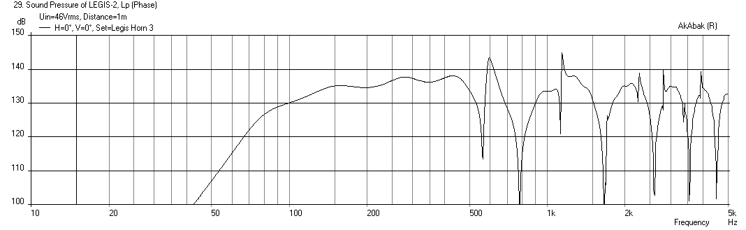
Label=30This code produced a response which looks like this (no wall effects with horn on floor in 2 pi space):
The corresponding SPL at xmax of 4.8mm and 55v (with high pass filter at 75 Hz) is quite impressive:
If you place the horn 2 m in front of a back wall, the wall reflections make the output at 0deg in front look like this:
Legis then asked if either a sealed chamber behind the drivers could be added, say 30 liters, or maybe a leaky box with a resistive vent to produce a cardioid response. I proceeded to model that and produced the following results:
Case (a) open back:
Case (b) sealed 30 liter back chamber with Q=0.5:
Case (c) 30 liter back chamber with 4 in dia x 10 in long vent:
What I noticed that was interesting was that the open back case actually loads the cone better than the sealed back chamber, as can be seen from the cone excursion plots of each case at 55 volts (the drive voltage needed to hit xmax for the open back case):
Case (a) cone excursion for open back:
Case (b) cone excursion for sealed back (30 liters):
Case (c) cone excursion for 30 liter chamber with 4 in dia x 10 in long vent:
Here are the polar responses for 100 Hz, 200 Hz, and 500 Hz at 4 meters away for the above cases:
Open back polar:
Sealed 30 liter chamber closed back polar:
Vented back polar:
I am now working on the effects of a resistive vent back similar to the one posed by Legis as illustrated here:
If you "Synergize" this with a compression chamber and injection port for each driver (still open back) and the addition of a B&C DE-250 CD XO at 1600Hz at the vertex you get this:
More info in post #156: http://www.diyaudio.com/forums/subwoofers/258706-study-dipole-cardioid-bass-horn-16.html#post3999668
Attachments
-
 Legis-horn-displ-open-back.png26.1 KB · Views: 3,471
 -
 Legis-horn-displ-sealed-back.png24.4 KB · Views: 3,454
 -
 Legis-horn-displ-vented.png26.3 KB · Views: 3,420
 -
 Legis-horn-Polar-open-back.png27.8 KB · Views: 3,403
 -
 Legis-horn-Polar-vented-back.png26.9 KB · Views: 3,413
 -
 Cardioid-horn-diag.png5.8 KB · Views: 3,411
 -
 Legis-horn-Polar-sealed-back.png24.4 KB · Views: 3,444
Last edited:
Hi,
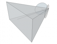
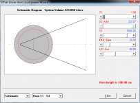
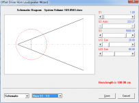
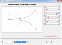
I might be wrong but I thought when you enter height and width, the values are converted to a 1D area, and Akabak is limited to conic and exponential expansion? What is the default expansion? See attached examples.
As a result I think you are modeling something more like this?
I might be wrong but I thought when you enter height and width, the values are converted to a 1D area, and Akabak is limited to conic and exponential expansion? What is the default expansion? See attached examples.
As a result I think you are modeling something more like this?
Attachments
Last edited:
Hi,
I might be wrong but I thought when you enter height and width, the values are converted to a 1D area, and Akabak is limited to conic and exponential expansion? What is the default expansion? See attached examples.
As a result I think you are modeling something more like this?
I believe there are three types of waveguides in AkAbak: linear where the area expands linearly as a function of distance along the waveguide (no specifier), conical where the area expands quadratically like a pyramid ("conical" specifier), and exponential where the expansion follows an exponential function set with a "T" value. I have built linear horns based on an AkAbak sims and the result is quite accurate.
Can you post what HR predicts for the same V horn? It may be that I have this sitting on the floor and that acts as an extension of the horn as a plane of symmetry reflection surface. In HR when you set 2 pi does it assume that the mouth exits a plane wall acting as the 2 pi boundary? Also, are you looking at power or pressure? AkAbak is showing pressure along 0 deg axis at a height of the centerline of the horn or 0.25 meters above the ground. The ground plane makes a difference. I could turn off all reflections and plot it in 4pi steradian space and that maybe something that is easier to compare to?
AkAbak has a tough steep learning curve, but the ability to place a radiator from a vent, waveguide, or cone arbitrarily at any x,y,z location angled at theta, phi, psi, that is, 6 deg of freedom is very powerful and needed if one is looking at the effect of multiple horns, vents, or cones as in dipoles and cardioids. Also the effect of floor and wall reflections are easily implemented.
Last edited:
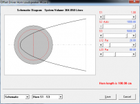
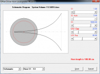
It looks like the default expansion is exponential when not specified:
I don't think parabolic expansion is supported:?
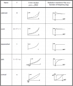
Akabak Manual PDF page 195 said:Parameter
Waveguide Keyword
'...' Identifier
Node=s=t Network node of the Waveguide. The volume velocity at the entrance - the funnel throat - 'flows' from pole s to ground and at the outlet - the funnel mouth - from pole t to ground.
T= (Optional) Parameter of horn function (Eqs. 1,2), as described for the element Horn.
If T is not entered, the program sets T=1, thus specifying a purely exponential horn function.
If the keyword Conical has been entered, the value of T is ignored.
range: 0<=T<=100
T= 0 catenoid
0 < T < 1 cosh
T= 1 exponential (default)
1 < T < 100 sinh Conical (Optional) If entered, the horn function describes a conical horn profile (see above). If the parameter T has been entered, it is ignored.
I don't think parabolic expansion is supported:?
Attachments
Last edited:
NEODan,
Thanks for pointing that out. Hmm... a linear expansion can be approximated by exponential for short distances - and you may be right about why the HR is different. When specifying conical isn't that the same as parabolic? As conical horns follow a quadratic or parabolic expansion.
Thanks for pointing that out. Hmm... a linear expansion can be approximated by exponential for short distances - and you may be right about why the HR is different. When specifying conical isn't that the same as parabolic? As conical horns follow a quadratic or parabolic expansion.
I removed the back chamber volume to illustrate the difference in volume between the expansions. Also you can see the resulting area at S2 is quite different.
If Akabak could do parabolic I'd be very familiar with it...
If Akabak could do parabolic I'd be very familiar with it...
Attachments
xrk. we had this discussion a short while ago (for the who knows what time). Con expands with a linear radius expansion (think traffic cone). PAR expands with a linear AREA expansion. thus, Par can be built out of straight plywood, with 2 "sides" parallel to each other. Con can not be built in this fashion.
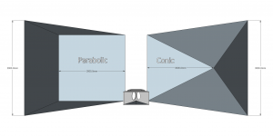

Like so:
Edit, I just read the manual again and terminology used by Akabak is different than what I am used to. Conical is linear expansion.
Manual p 186 states:
The conical horn is the simplest horn shape. The cross-section increases linearly.
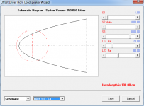
I will redo with conical turned on and see what happens.
Last edited:
My previous understanding of conical (i.e., all sides expanding like the inside of a four sided pyramid) has a quadratic area dependence with axial distance. But in Akabak, they use it to call a linear (or similar to HR "PAR") expansion. If you use PAR we can compare results if I use the "CONICAL" switch.
Edit: I just tried it with the "CONICAL" switch turned on and it did not make much of a difference. Conical increased max SPL by about 1dB at 100 Hz. I think over the short axial run vs throat/mouth area, the exponential horn approximates a linear expansion horn very well.
Edit: I just tried it with the "CONICAL" switch turned on and it did not make much of a difference. Conical increased max SPL by about 1dB at 100 Hz. I think over the short axial run vs throat/mouth area, the exponential horn approximates a linear expansion horn very well.
Last edited:
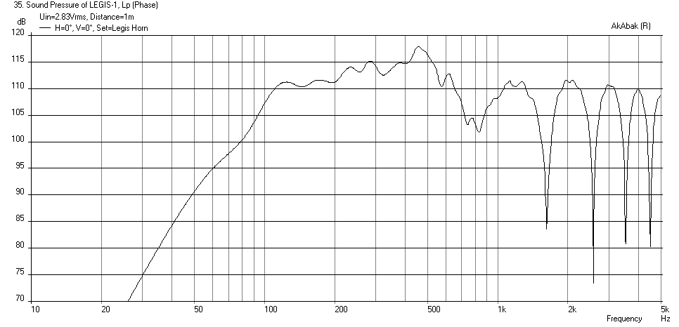
Here is the sim of the horn with 30 liter sealed back chambers with all reflections turned off for 4 pi steradians. This gives about -3dB less as expected vs 2 pi. I think it may be the fact that I was accounting for the horn sitting on the ground with its axis 0.25 m above the ground that may have enhanced the response compared to HR. I am driving this at 46 volts at xmax of 4.8 mm for the sealed back case.
Attachments

Effect of Resistive Rear Vents on Polar Response
I added resistive vents to the back chambers to the model. This was done using a "waveguide" element for the vent in order to use the Acou_Resistance option that specifies the resistive pressure loss through the vent. The pressure loss is specified as Pa*sec/m per m^2 or Pa/(s m^3). I use a typical value of 5000 Pa/(s m^3) corresponding to a medium dense poly-batting. I set the vent area for two cases 15 in x 15 in ea and 2 in x 15 in ea x 4 in long (thickness of damping material). For the placement and orientation of the vents, I set the side firing ones at 0.5 m back from the mouth, and the rear firing ones at 1 m back from the mouth. The side firing ones I have two cases of 90 deg and 60 deg. The rear firing ones were only at 180 deg. There are a lot of cases and changes to the angle of the vents and the vent area really have an impact on the polar pattern. Additionally, when the vents are too large in CSA, a cancellation dip in the zero deg frequency response is seen around 162 Hz. Making the vent CSA smaller from 15 in x 15 in to 2 in x 15 in really improved the situation.
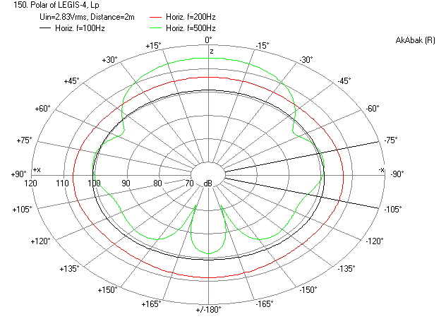
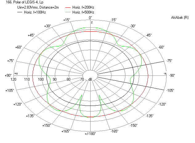
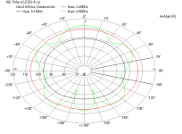
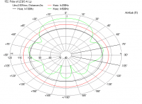
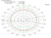
Polar Responses for 100 Hz, 200 Hz, 500 Hz at 2 m:
Case (a) Open back baseline:
Case (b) Dual 15 in x 15 in Resistive ports at 90 deg:
Case (c) Quad 15 in x 15 in ports at 90 deg and 180 deg:

Case (d) Dual 15 in x 15 in ports at 60 deg:

Case (e) Dual 2 in x 15 in ports at 60 deg:
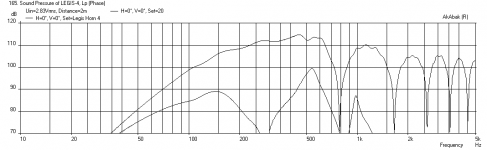
Zero-deg Freq Response at 2 m:
Case (d) dual 15 in x 15 in ports at 60 deg:
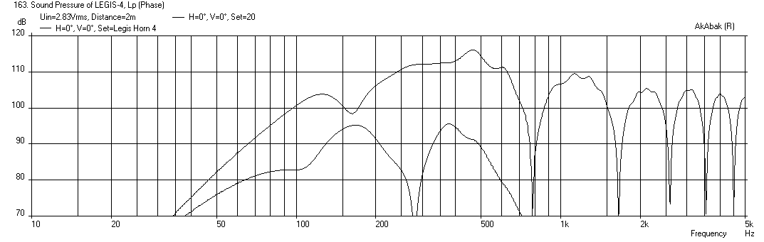
Case (e) dual 2 in x 15 in ports at 60 deg:
I think having the smaller 2 in x 15 in ports is important for reducing the cancellation at 162 Hz. The polar response appears to be semi cardioid with some mild lobing and a peak-lobe at 180 rather than a null as in a true cardioid. I think a true cardioid may be difficult to achieve with this particular configuration of horn and two drivers and vents.
Here is the script if anyone is interested in playing with it:
I added resistive vents to the back chambers to the model. This was done using a "waveguide" element for the vent in order to use the Acou_Resistance option that specifies the resistive pressure loss through the vent. The pressure loss is specified as Pa*sec/m per m^2 or Pa/(s m^3). I use a typical value of 5000 Pa/(s m^3) corresponding to a medium dense poly-batting. I set the vent area for two cases 15 in x 15 in ea and 2 in x 15 in ea x 4 in long (thickness of damping material). For the placement and orientation of the vents, I set the side firing ones at 0.5 m back from the mouth, and the rear firing ones at 1 m back from the mouth. The side firing ones I have two cases of 90 deg and 60 deg. The rear firing ones were only at 180 deg. There are a lot of cases and changes to the angle of the vents and the vent area really have an impact on the polar pattern. Additionally, when the vents are too large in CSA, a cancellation dip in the zero deg frequency response is seen around 162 Hz. Making the vent CSA smaller from 15 in x 15 in to 2 in x 15 in really improved the situation.
Polar Responses for 100 Hz, 200 Hz, 500 Hz at 2 m:
Case (a) Open back baseline:
Case (b) Dual 15 in x 15 in Resistive ports at 90 deg:
Case (c) Quad 15 in x 15 in ports at 90 deg and 180 deg:
Case (d) Dual 15 in x 15 in ports at 60 deg:
Case (e) Dual 2 in x 15 in ports at 60 deg:
Zero-deg Freq Response at 2 m:
Case (d) dual 15 in x 15 in ports at 60 deg:
Case (e) dual 2 in x 15 in ports at 60 deg:
I think having the smaller 2 in x 15 in ports is important for reducing the cancellation at 162 Hz. The polar response appears to be semi cardioid with some mild lobing and a peak-lobe at 180 rather than a null as in a true cardioid. I think a true cardioid may be difficult to achieve with this particular configuration of horn and two drivers and vents.
Here is the script if anyone is interested in playing with it:
Code:
| ### Model of Legis open back dual driver 1 m x 1m x 50 cm high horn with Dual Deltalite 15's
| by xrk971
| July 5, 2014
| Version 4 includes rear chamber and 4 resistance vents for cardiod horn

System 'Legis Horn 4'

Def_Const

{

| ### input parameters ###

| ### Define exterior physical size of speaker

Width = 1.00  ;   | width at mouth in meters
Height = 0.50 ;   | height of speaker in meters
Depth = 1.00  ;   | depth of speaker from cusp to mouth in meters

Speaker_pos=0.25;  | Speaker height above floor in meters
Dist_wall=2000.0;     | Speaker distance from back wall in meters
Q=0.5 ;  | Q of back chamber
Backchamber_vol=30*0.001  ; | vol in liters

| *** Resistance duct gemoetry ****
Res_duct_width=2.0*0.0254;  | Res duct width in inches, height assumed to be same as horn panel
Res_duct_length=4.0*0.0254;  | Res duct length in inches
Damping=5000;  | Pascal sec per m per m^2 - pressure drop per unit area per meter

| Horn geometery

S0=0.01    ;  |width of vertex in meters (small value)
S1=0.173   ;  |width at driver center assuming 200 mm center to edge distance for driver in meters
L01=0.173  ;  |distance from vertex to driver on centerline cos(30deg)*200mm=173mm
S2=1.00    ;  |width at mouth in meters
L12=0.827  ;  |distance from driver at centerline to mouth in meters

}

Def_Driver  'Deltalite15'  | Eminence Model Delatalite II 15  4.8 mm xmax, 99.2dB, Qts 0.38
  SD=856.3cm2   |Piston
  fs=42Hz
  Mms=72g
  Qms=4.56
  Qes=0.41
  Re=5.29ohm
  Le=1.15mH
  Bl=15.7Tm
  Vas=204L


| Speaker with horn axis CL at Speaker_pos above floor and Dist_wall away from back wall
Def_Reflector  HorizEdge
Bottom={Speaker_pos}  Top={Dist_wall+Depth}
HAngle=0  VAngle=0

Filter 'HighPass' |Highpass filter -12dB/oct BW
fo=75Hz vo=1
{b2=1;
a2=1; a1=1.414214; a0=1; }


| Define driver to be used and wired in parallel (left driver when viewed from front
Driver Def='Deltalite15' 'Driver 1'
Node=1=0=11=201

| Right driver when viewed from front
Driver Def='Deltalite15' 'Driver 2'
Node=1=0=11=202

Enclosure  'Back chamber 1'  Node=201
Vb={Backchamber_vol}  Qb/fo={Q}  Lb=12in

Waveguide 'Resistance Duct 1' | Resistance duct left left, use waveguide to allow acoustic reistance element
Node=201=211
STh={Res_duct_width*Height}
SMo={Res_duct_width*Height+0.001} | Waveguide needs some small expansion
Len={Res_duct_length}
AcouResistance    'Damping1'  Node=201=211  Ra={Damping}  | Damping in Pa/m^2 per m or Pa/m^3

|OFF
Waveguide 'Resistance Duct 3' | Resistance duct left back, use waveguide to allow acoustic reistance element
Node=201=213
STh={Res_duct_width*Height}
SMo={Res_duct_width*Height+0.001}
Len={Res_duct_length}
AcouResistance    'Damping3'  Node=201=213  Ra={Damping}

Enclosure  'Back chamber 2'  Node=202
Vb={Backchamber_vol}  Qb/fo={Q}  Lb=12in

Waveguide 'Resistance Duct 2' | Resistance duct right right, use waveguide to allow acoustic reistance element
Node=202=212
STh={Res_duct_width*Height}
SMo={Res_duct_width*Height+0.001}
Len={Res_duct_length}
AcouResistance    'Damping2'  Node=202=212  Ra={Damping}

|OFF
Waveguide 'Resistance Duct 4' | Resistance duct right back, use waveguide to allow acoustic reistance element
Node=202=214
STh={Res_duct_width*Height}
SMo={Res_duct_width*Height+0.001}
Len={Res_duct_length}
AcouResistance    'Damping4'  Node=202=214  Ra={Damping}

| Resistance vent radiator left -90 deg
|OFF
Radiator  'Rear_Rad1'  Def='Resistance Duct 1'    Node=211
    x=-0.5m  y=0  z=-0.5m  HAngle=-60  VAngle=0
    WEdge={Width/2}  Hedge={Height/2}  Reflection
Label=10

| Resistance vent radiators left back 180 deg
OFF
Radiator  'Rear_Rad1'  Def='Resistance Duct 3'    Node=213
    x=-0.25m  y=0  z=-1.0m  HAngle=180  VAngle=0
    WEdge={Width/2}  Hedge={Height/2}  Reflection
Label=30

| Resistance vent radiator right +90 deg
|OFF
Radiator  'Rear_Rad2'  Def='Resistance Duct 2'    Node=212
    x=+0.5m  y=0  z=-0.5m  HAngle=+60  VAngle=0
    WEdge={Width/2}  Hedge={Height/2}  Reflection
Label=20

| Resistance vent radiators left back 180 deg
OFF
Radiator  'Rear_Rad4'  Def='Resistance Duct 4'    Node=214
    x=+0.25m  y=0  z=-1.0m  HAngle=180  VAngle=0
    WEdge={Width/2}  Hedge={Height/2}  Reflection
Label=40

| ### HORN WAVEGUIDE

Waveguide 'Horn Seg 1'  | From vertex to driver at node=11 (both drivers excite node 11
Node=10=11
STh={S0*Height}
SMo={S1*Height}
Len={L01}
CONICAL

Waveguide 'Horn Seg 2'  | From driver injection point to mouth
Node=11=12
STh={S1*Height}
SMo={S2*Height}
Len={L12}
CONICAL

| ### Main horn mouth radiator
Radiator  'Horn Mouth'  Def='Horn Seg 2'    Node=12
    x=0  y=0  z=0  HAngle=0  VAngle=0
    WEdge={Width/2}  Hedge={Height/2}  Reflection
Label=50
Attachments
-
 Legis-4-resistive-back-dual-60deg-15in-Freq-0deg-2m.png28.9 KB · Views: 1,699
 -
 Legis-4-resistive-back-dual-60deg-2in-Polar-2m.png26.7 KB · Views: 1,711
 -
 Legis-4-resistive-back-dual-60deg-15in-polar-2m.png25.4 KB · Views: 1,718
 -
 Legis-4-resistive-back-quad-90-180deg-15in-4in-long-polar-2m.png25.4 KB · Views: 1,734
 -
 Legis-4-resistive-back-dual-90deg-15in-4in-long-polar-2m.png25.6 KB · Views: 1,737
 -
 Legis-1-open-back-polar-2m.png25.2 KB · Views: 1,746
 -
 Legis-4-resistive-back-dual-60deg-2in-Freq-0deg-2m.png28.5 KB · Views: 1,698
Last edited:
Thank you for the sims and moving the discussion under it's own topic.
Personally I find it very interesting how the polar response of open backed horn does not represent dipole figure-8 radiation at all in the lower frequencies. It is like true omni at 100Hz. How is that possible?
Resistive porting does not seem to enhance sensitivity at all (which I hoped), quite on the contrary!
"Dipole"/open backed horn with rear wave damping (without back chamber) is another idea that could translate into more of a cardioid polar pattern but maybe without the (estimated) sensitivity loss of resistive porting. It could be done with placing thick damping material right around the woofers, complemented with regular front wall acoustic treatment/damping.
I ordered 4pcs of Deltalite II 2515's so the empirical tests") smash can start at some point.
smash can start at some point.
Personally I find it very interesting how the polar response of open backed horn does not represent dipole figure-8 radiation at all in the lower frequencies. It is like true omni at 100Hz. How is that possible?
Resistive porting does not seem to enhance sensitivity at all (which I hoped), quite on the contrary!
"Dipole"/open backed horn with rear wave damping (without back chamber) is another idea that could translate into more of a cardioid polar pattern but maybe without the (estimated) sensitivity loss of resistive porting. It could be done with placing thick damping material right around the woofers, complemented with regular front wall acoustic treatment/damping.
I ordered 4pcs of Deltalite II 2515's so the empirical tests
smash can start at some point.
Last edited:
Below 200 Hz the sound radiation is semi omnidirectional in general. Certainly below 100 Hz it is hard to tell where the source is unless you are right in front of it. I think with a large flat baffle and dipole you may see a figure 8 pattern for 200 Hz. I think the case with the smaller 2x15 in vents looks good and gives a smoother response than the open back case.
Good to hear that you ordered the drivers. Looking forward to how the experiments come along.
Good to hear that you ordered the drivers. Looking forward to how the experiments come along.
I believe you've seen this: 6moons industry features: La Grande Castine
And, this is not as 'popular', but I think it's equally interesting: (new adventures in) ultra‑fi: tumbling dice: experimenter’s lower-mid horns
And, this is not as 'popular', but I think it's equally interesting: (new adventures in) ultra‑fi: tumbling dice: experimenter’s lower-mid horns
CLS,
Thanks for the link to the 6Moons article. No, I had not seen this before. Very impressive and it looks about similar in size. Doesn't surprise me that they say it goes only down to 80Hz. I set my HPF in the sim at 75 Hz. The 2 in Radian CD and horn to go from 500 Hz up is impressive to see mated to a concrete spherical horn. Now that we see a setup like this actually produced and sold I have no doubt the design sketched by Legis will work. The 110 dB sensitivity is pretty cool.
Thanks for the link to the 6Moons article. No, I had not seen this before. Very impressive and it looks about similar in size. Doesn't surprise me that they say it goes only down to 80Hz. I set my HPF in the sim at 75 Hz. The 2 in Radian CD and horn to go from 500 Hz up is impressive to see mated to a concrete spherical horn. Now that we see a setup like this actually produced and sold I have no doubt the design sketched by Legis will work. The 110 dB sensitivity is pretty cool.
- Status
- This old topic is closed. If you want to reopen this topic, contact a moderator using the "Report Post" button.
- Home
- Loudspeakers
- Subwoofers
- Study of a Dipole/Cardioid Bass Horn