Into the simulator i could not see problems removing the feedback electrolitic
condenser and substituting the one by a jumper of wire... a short in the place of the condenser... so....no more condenser.
I would like to understand the reasons everybody uses that baby elefant there?
Well.... this was simulator.... in some days.... maximum a week, i will be listening and swithing this condenser installing into the circuit and shorting it..... better.... to include and substitute by a short, this way will be better because i will insert it into the circuit already charged.
regards,
Carlos
wood finish
Carlos,
Many good comments about wood finishes have been posted. I'd like to add that an oil finish is "in" the wood. The wood remains accessible to touch. Lacquer, shellac, polyurethane and others build a coating "on" the wood. The wood is covered.
I like to be able to feel the wood.
Carlos,
Many good comments about wood finishes have been posted. I'd like to add that an oil finish is "in" the wood. The wood remains accessible to touch. Lacquer, shellac, polyurethane and others build a coating "on" the wood. The wood is covered.
I like to be able to feel the wood.
Yes Ed .... better to be in the wood.. inside the wood, under the wooden skin.
I was thinking about.... after start sanding i tried those oils we use into the kitchen.... result very pretty... and i could not remove it using sandpaper.
Because inside the wood, not a cover.... so.... we use to put lawyers or varnish to protect the wood against to be pretty!...ahahahah... very interesting that.
If already oiled...no one need to worry about food that may fell down over the table, penetrating into the cloth cover and will stop into the already oiled wood..... so.... really... the oil is the best idea.... will not be shinny, but really, things shinny show all defects, all imperfections appear....not too shinny is better, and oil can make that.
Problem is to find the oil.... this Danish oil do not exist here..but maybe another one... i will see what i can find.
regards,
Carlos
....................................................................................................
About the condenser, into the feedback line, the gain network is adjustable there.... preset is unitary gain, gain one....but the resistance in series with the condenser will increase the gain.
Also, i was thinking about.... we can adjust, or at least we can attenuate bass into this network, reducing the electrolitic condenser value.... so.... we have some resource using the condenser there, because of capacitive reactance... the resistance condensers creates to low frequencies.
If we remove.... everything will be flat... sometimes we do not want completelly flat.... it is a good idea to reduce subsonics when constructing a sub woofer, not to waste energy into frequencies we cannot listen... not to creating heat that will not be producing sounds we can listen.... i see those condensers have a good reason to exist there..... about DC block...i do not think it makes a needed job into this matter... the lowest the resistance, even this way will be big compared to the speaker...so will not be loading nothing.
I would like to listen Graham Maynard and Andrew T about this subject.
Please...go ahead!
regards,
Carlos
Hi,
there are two DC blocking capacitors in an amplifier ( Push pull dual polarity topology).
The input filter is a DC block from the source and also removes the source resistance from the input which only sees Zin.
The NFB filter is a DC block from the output and reduces the gain of the amplifier to 1 at DC. This ensures the other input sees only Rfb.
These two DC blockers must be matched so that the input filter controls the bandwidth of the amp and the NFB should be at least half an octave lower.
If one wants to experiment with removing either of these capacitors then to preserve the DC operating points of the input LTP, BOTH DC blockers should be removed.
Removal of only one causes a mismatch that increases the output offset, sometimes substantially.
Removal of both can also cause a problem if the source resistance is accidently removed or blocked. eg by disconnecting the pre to power interconnect or swapping to a pre that has it's own DC blocker installed.
I do not advise removal of either blocker unless you carefully assess the pros AND cons and just how bad the offset becomes when DC conditions are not properly matched. DC servos can overcome part of the problem, but one is still left with the disconnection possibility. The improvement in sound quality, if any, could be worth the risk. Make up your own mind, but do not wade in and make uninformed decisions.
Hi Carlos,
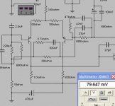
When I simulate your DX amp with the input capacitor shorted, the standing load current (8ohm) goes from uA to about 15mA.
If I short the NFB capacitor then the standing load current becomes 0.5A !!!
If I short both capacitors, with input series input R to the first base the same as the NFB resistor to ground as Andrew suggests, then the balance could be better and load current low, however, any tuner signal fading, or CD AD/DAC inadequacies are likely to drive a LS cone beyond safe limits and deleteriously modulate reproduced audio.
CDs can potentially reproduce to very low frequencies, which means that recording system flaws which might be filtered out by amplifier input and NFB capacitors can then ruin reproduction.
Cheers ............Graham.
caps
Dear Carlos,
please don't get me wrong - I do not want to criticize your circuit but rather would like to exchange some ideas and thoughts and maybe contribute a little.
Andrew, I see the point that shorting the cap in the feedback path changes the DC operating conditions and turns them asymmetric.
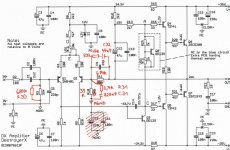
Let me propose a simple idea how to handle this situation, see the attached image, where I took the liberty to make some modifications in the DX amp schematic from Greg's website - Greg, please excuse.
In this I made the following changes:
- C10/C11 are shorted
- R10 is changed from 2k2 to 39k
- R11 is changed from 39k to 680k
- R3 gets another 680k in parallel
At this point the DC operating condition is again symmetric,
but the feedback resistor of 680k is very high impedance and I suspect that this will increase the amplifier output noise significantly.
Therefore I added further
- 2.7 kOhms in a series with 820nF in parallel to R10
- and 47 kOhms in a series with 47nF in parallel to R11
The purpose of these is to lower the feedback impedance at higher frequencies in order to reduce noise.
The ratios 820nF / 47nF, 680k / 39k, 47k / 2.7k are all the same and need to be matched. In this way the feedback divide ratio is constant over frequency. Because of that, the corner frequency of the RC in the feedback is not critical; here it is set to 72 Hz - below this frequency, noise increases at 6 db / octave up to the limit given by the DC feedback. This low frequency noise increase should be inaudible due to low frequency insensitivity of the ear.
With this feedback circuit, the output DC offset will for sure be higher than in the original version, but given the low offset of the original circuit, it should still be okay, I believe.
Carlos, Andrew, Graham, what do you think of this idea?
It may be worth a try just to see what is the impact of the electrolytic cap C10 on sound quality.
Kind regards
----------------
konkret
Dear Carlos,
please don't get me wrong - I do not want to criticize your circuit but rather would like to exchange some ideas and thoughts and maybe contribute a little.
Andrew, I see the point that shorting the cap in the feedback path changes the DC operating conditions and turns them asymmetric.
Let me propose a simple idea how to handle this situation, see the attached image, where I took the liberty to make some modifications in the DX amp schematic from Greg's website - Greg, please excuse.
In this I made the following changes:
- C10/C11 are shorted
- R10 is changed from 2k2 to 39k
- R11 is changed from 39k to 680k
- R3 gets another 680k in parallel
At this point the DC operating condition is again symmetric,
but the feedback resistor of 680k is very high impedance and I suspect that this will increase the amplifier output noise significantly.
Therefore I added further
- 2.7 kOhms in a series with 820nF in parallel to R10
- and 47 kOhms in a series with 47nF in parallel to R11
The purpose of these is to lower the feedback impedance at higher frequencies in order to reduce noise.
The ratios 820nF / 47nF, 680k / 39k, 47k / 2.7k are all the same and need to be matched. In this way the feedback divide ratio is constant over frequency. Because of that, the corner frequency of the RC in the feedback is not critical; here it is set to 72 Hz - below this frequency, noise increases at 6 db / octave up to the limit given by the DC feedback. This low frequency noise increase should be inaudible due to low frequency insensitivity of the ear.
With this feedback circuit, the output DC offset will for sure be higher than in the original version, but given the low offset of the original circuit, it should still be okay, I believe.
Carlos, Andrew, Graham, what do you think of this idea?
It may be worth a try just to see what is the impact of the electrolytic cap C10 on sound quality.
Kind regards
----------------
konkret
Attachments
Good and very clear answer..thank you.
also thanks by Konkret presence, Gaetan and Harry3
I do not feel problem on that.... i suggest you to try that modification Konkret, sorry, i have not motivation...i was listening the Dx amplifier, the standard one, compared to the new Dx Precision and i feel it so nice, so warm, so good sonics...that really, i do not have the desire to modify it..... it is nice.
But all ideas can be tried in my next one... the Dx Precision...and i will make them to listen soon....now i am sanding my dinner wooden table...ahahahah.
Harry3....i cannot see problems, those things instruct us a lot...maybe a link will be better because i do not know how forum management see those things..if good or not...if has copyrigth or not...if turns forum more rich or a copy or magazines.... i really have doubts....it is up to you to decide.
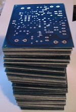
Every instructive things are welcome.... we are in a break.... people waiting boards to construct the High Resolution II.... Precision not release...and this opens those conversations...this turns the gap filled.....good...i feel it good.... do not know about the forum management ideas about.
regards,
Carlos
also thanks by Konkret presence, Gaetan and Harry3
I do not feel problem on that.... i suggest you to try that modification Konkret, sorry, i have not motivation...i was listening the Dx amplifier, the standard one, compared to the new Dx Precision and i feel it so nice, so warm, so good sonics...that really, i do not have the desire to modify it..... it is nice.
But all ideas can be tried in my next one... the Dx Precision...and i will make them to listen soon....now i am sanding my dinner wooden table...ahahahah.
Harry3....i cannot see problems, those things instruct us a lot...maybe a link will be better because i do not know how forum management see those things..if good or not...if has copyrigth or not...if turns forum more rich or a copy or magazines.... i really have doubts....it is up to you to decide.
Every instructive things are welcome.... we are in a break.... people waiting boards to construct the High Resolution II.... Precision not release...and this opens those conversations...this turns the gap filled.....good...i feel it good.... do not know about the forum management ideas about.
regards,
Carlos
Hi konkret,
What you are suggesting sounds like impedance in series with the NFB sense.
This is not something I have tried, but then nor would I want to either, for my prime aim with NFB is good phase linearity of loudspeaker damping with respect to input audio waveform input.
Cheers .......... Graham.
What you are suggesting sounds like impedance in series with the NFB sense.
This is not something I have tried, but then nor would I want to either, for my prime aim with NFB is good phase linearity of loudspeaker damping with respect to input audio waveform input.
Cheers .......... Graham.
Hi Graham,Graham Maynard said:When I simulate your DX amp with the input capacitor shorted, the standing load current (8ohm) goes from uA to about 15mA.
If I short the NFB capacitor then the standing load current becomes 0.5A !!!
you have simulated what I have called mixed AC/DC coupling.
These hybrids are potentially very damaging. Don't!!!
But it can get even worse.
If the input LTP has been set up with unbalanced emitter currents then the output offset varies, it varies even more with temperature changes.
Anyone intending to go to fully DC coupled or mixed AC/DC coupling should/must fit an output offset detector and safety relay and/or power shutdown.
Re: caps
increasing the feedback pair satisfies the DC operating condition.
But, look back to my response to Graham's simulation of the two hybrid coupling options.
You're suggestion works for a perfectly set up LTP and for transistors that stay permanently at one unvarying temperature. The DC gain of the amplifier and the variable semiconductor temperatures WILL give rise to a very variable output offset. At least it should never be as bad as that 500mA that Graham predicted in his worse performing model.
Graham,
can you sim this modification?
Hi,konkret said:........Let me propose a simple idea how to handle this situation, see the attached image, where I took the liberty to make some modifications in the DX amp schematic from Greg's website - Greg, please excuse.
In this I made the following changes:
- C10/C11 are shorted
- R10 is changed from 2k2 to 39k
- R11 is changed from 39k to 680k
- R3 gets another 680k in parallel
At this point the DC operating condition is again symmetric,........................With this feedback circuit, the output DC offset will for sure be higher than in the original version,.........
increasing the feedback pair satisfies the DC operating condition.
But, look back to my response to Graham's simulation of the two hybrid coupling options.
You're suggestion works for a perfectly set up LTP and for transistors that stay permanently at one unvarying temperature. The DC gain of the amplifier and the variable semiconductor temperatures WILL give rise to a very variable output offset. At least it should never be as bad as that 500mA that Graham predicted in his worse performing model.
Graham,
can you sim this modification?
Is that similar to Leach's Lo Tim?peranders said:I can't see the advantage either to use such a feedback network. It seems more safe to have a plain voltage divider with a possible fork to the driver transistors so you'll let the output transistors run without feedback at > 1MHz.
Harry3 said:Am I allowed to post articles from magazines for reference on this thread or will I get shot?
Hi
I agree with Carlos, I don't see any problems and it can be instructive for many of us.
But if you hesitate to post it you can send it by email to those who ask it, for myself I would be interest to see it.
Than
Bye
Gaetan
- Status
- Not open for further replies.
- Home
- Amplifiers
- Solid State
- Destroyer x Amplifier...Dx amp...my amplifier