For Max RMS power related to load driving capability.
Watch 20Hz, 100Hz, 1kHz or 10kHz sine waveform on a scope as developed across a nominal resistor value, of say 4 or 8 ohms.
Sometimes an 8 ohm amplifier will produce greater output into 5 or 6 ohm loads; 2.5 or 3 for 4 ohm amplifiers.
If you watch carefully with a magnified display for the onset of peak flattening -clipping- you know this is the maximum output at the point where reproduction will become noticeably distorted.
Use the scope to measure the peak to peak voltage and divide by 2.828 to get RMS, or measure with an AF voltmeter.
Square the RMS voltage and divide by the ohms value of the load resistor. This gives you the max power rating for the load measured.
You can build up power curves for different load values at different frequencies.
NB unless your amplifier is class-A this measurement should be made as quickly as possible in order to minimise output-stage device overheating.
Cheers ......... Graham.
And the most simple and easy way.
Read your speaker impedance...not knowing, measure your speaker resistance and make it match the standards of 4 ohms and 8 ohms.... it will be around those numbers.
Install your Multimeter, with the tips attached into the speaker terminals.
Play loud music, and your AC Voltimeter will be showing overflow...your numbers will be changing all time long.... the music must have bass....ans strong bass, because those cheap multimeters read frequencies till 400 hertz..... precision is from 50 to 400 hertz only.
So.... the components of bass you have, the ones constitutes the biggest power you may have (around 70 percent) will be displayed... collect the maximum value of voltage and multiply this value by itself (square) and divide by the speaker impedance.
This will be the maximum power your speaker will hold without distort...and this related the main powered frequency...the bass frequencies...if you want to know your power, you can include 30 percent in this result.
To measure the amplifier maximum power (not beeing disturbed by the speaker limits of power)... install a 8 ohms resistance into the output...or a 4 ohms resistance.... the one must be bigger in power dissipation not to burn.... but 20 watts will be good enougth if you make those testings fast....if you have a Scope to watch the waveform clipping, use it....not having...use the sketch i am providing and listen the modifications the sound produces when the amplifier start to clip...it is easy and clear to perceive when it is clipping.
Of course, having generator and scope will be better...this is the poor man method..something everyone can use in emergencies.
You are using 25 volts supply..... so...your power will be smaller
Maybe you can use those free softwares that produces tones.... signal generators.. this way you can use this signal from the computer to the amplifier.... use sinusoidal sign.... 20 Hertz, 1Khz and 17.7 Kilohertz (human audition extremes under normal levels and the most sensitive frequency for males)
regards,
Carlos
Attachments
Had some fun in the sun today, spraying hammertone on the backpanel... it is still drying but looks like will come out fine...
I am still thinking about if I should make the heatinks black... suppose I should wait to see what the final colour of the front is once the varnish is on the wood.
Edit... thats better...
I am still thinking about if I should make the heatinks black... suppose I should wait to see what the final colour of the front is once the varnish is on the wood.
Edit... thats better...
Thanks Nordic..... the word was removed.
I understood.
To paint the heatsinks may be a problem.... will be needed special material not to be destroyed by the time, heat (warmth) or scratches.
It will turn awful when scratched!
Normally the aluminium receive electro-chemical treatment to turn black.
I do not remember the chemical...maybe Oxálic Acid..... a weak solution using watter to dilute, applied into the aluminium produces enormous reaction and turn the aluminium surface white without bright.
Very pretty result....but i cannot remember if the name is Oxálic...it is used to clean clothes...skirts, pants....well... those things.
There's a solution used to clean aluminum pots....those used to cook food.... this solution is wonderfull too, but a little weak.
regards,
Carlos
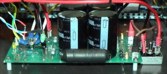
This is the Dx supply suggested, constructed by our friend Rabbitz.
He used a spare board he had, provided by Anthony Holton, from Aussie Amplifiers.
The board is strong, double face, excelent material used there...and them Rabbitz adapted the Dx circuit.
He said that sounds special.... better than the more simple supplies.
Simple supplies do not result fine.... i have made tests too.... big condensers, inductors and snubbers helps a lot.
regards,
Carlos
Attachments
hmmm I know what you are talking about... I know some people use mild caustic soda (lye) mixtures to do the same thing...
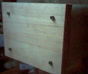
Here is a picture of the front... I may still recess the nuts and put washers on like the rear... also the colour is a bit wrong in the picture... it is meranti, from that old backdoor, that I glued to make a face...it is slightly redish.
Here is a picture of the front... I may still recess the nuts and put washers on like the rear... also the colour is a bit wrong in the picture... it is meranti, from that old backdoor, that I glued to make a face...it is slightly redish.
Attachments
Yes Hartono..when using electricity the process is called this way.
There are chemical processes too... we cook the metal with the correct salt (turn hot to make it faster)...... but at the end, anode will work to...if not external provided, will be the product or metal polarity.
Used to produce the black colour ( A little blue maybe) you have in weapons....the old ones, as today they are using Plastic material to weapons too.
Sheldon would be helpfull in those moments...bad luck, he is busy with Parker designs and not following this thread.
regards,
Carlos
The anodised surface is full of tiny holes.Hartono said:cool....I didn't know we can use chemical to change metal colour.....I'm interested......
The dyeing process infills these holes with colour and then you fix that colour.
Hectic... too many options... I know the black has a significant improvement of the heatsink's rateing, but my tested unit did not get very hot anyway.
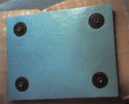
Here is a picture of the back... it is the same colour as the power supply... the transformer case's colour came out better in its photo.
I must still sleep on connector positions... which willl probably be a waste of time, compared to just going to the shop tommorrow and looking at what I can actualy get.
Attachments


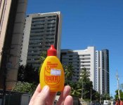
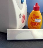
The white result is hard to capture into digital images
As it is not too much different from the normal aluminium surface we know.
It looses the bright and turns white only.
The bottle has the advice that is dangerous to the health.
regards,
Carlos
As it is not too much different from the normal aluminium surface we know.
It looses the bright and turns white only.
The bottle has the advice that is dangerous to the health.
regards,
Carlos
Attachments
Ecat.... i am thinking you have faced problems.... if happened this way
relax.... this is very common.... very difficult to me to assemble and the unit goes working in the first testing.
Normally i miss something.... very common that.
Invertion of parts.... errors in resistance values.... wrong condenser polarities... damaged parts, errors in transistor leads.... too much current burning parts in the first set up (when we forgot the protective resistances)...polarity invertions, small shorts, copper line interrupted.
Well.... a lot of things happens, what i have said is just a small sample of things that happens.
I hope i am wrong....but if you had problems, please, come to us...or go directly to my mail.... i will be happy to help.
panzertoo@yahoo.com
regards,
Carlos
- Status
- Not open for further replies.
- Home
- Amplifiers
- Solid State
- Destroyer x Amplifier...Dx amp...my amplifier