jacco vermeulen said:
btw: i've heard both the kSA50 and the KSA100 on proper loudspeakers.
The KSA100MKII may have been better on Apogee's, i've never understood the charm of those metal washboards.
or very big cheese graters

"family size"
or morgue table
allan
We dont want to wait for another 2 years
Mark:
 Yes, to me it sounds like a good idea to make a MK-2 board with only minor changes due to the component substitutions and output board connections etc. Then the boards could be made in a relative decent time period and also to an acceptable fair price, dont you think?
Im in for 6 boards of the KSA100 MK-2.
Regards
Mark:
As for the PCB if we make up a MK-2 board straight over it would be easily reverse-adaptable to building any of the earlier KSA-100 circuits. Neither myself, Al, or my friend Dave have time to adapt or figure out a universal pcb to accomodate all the versions. I am only willing to foot the bill to have 100 boards made up. Its easy to envision that the Mk-2 board straight over can be very adaptable in itself just by jumpering out certain devices and changing some part values to building the earlier versions of the amp. Hopefully those that are going that route would take the time to share that in a future chart with all of us. However it should be up to each individual building the amp to figure out for him self..... Otherwise this PCB deisgn might go on for two years! So in simple terms the universal board would already exist in the from of the MK-2 board!!
Yes, to me it sounds like a good idea to make a MK-2 board with only minor changes due to the component substitutions and output board connections etc. Then the boards could be made in a relative decent time period and also to an acceptable fair price, dont you think?Im in for 6 boards of the KSA100 MK-2.
Regards
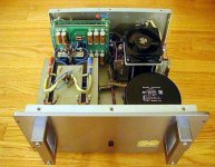
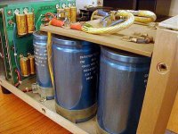
Interesting power supply
Hi Mark
Any idea for what reason Krell used a power supply regulator ?
Was its purpose to rise the efficiency of the output stage
(this could be done by having a 5-10V higher rails on the input/driver stage)
Or was the purpose to lowering power supply ripple noise/buzzing?
Maybe both.
A long time ago I built a Pass 40W Class-A and implemented a solution similar like the Krells (I think but Im not sure about that). I think I used a regulator for ± 7-8 volt higher/lower than for the power devices who was darlingtons).
The benefit for doing it for me was lowering power supply noise AND a rise in power output capability, thus rising the efficiency of the amp (also: rising the total audio quality )
Wandering if this implementation should be located together on the amps driver board ?
It could be done though its not a high power circuit. Or is it impractical?
(benefit: you only need to make one board, not two. drawback: a more complex board/circuit)
What do you think?
Regards
Mark A. Gulbrandsen said:
So that being said all that need be changed are those devices over to the Zetex unless anyone knows of a better device (I had originally thought of IRF9610 and 610 but the Zetex's spec better).
Mark
I have been experimenting with jfets on my Aleph 3 and found those are much more musical than the zvp3310a.
I am using the j176 jfet and do not know its complimentary version, but there are a whole range of mA versions for more or less driver power. It seems to be more spacious and much more extended in the highs with less distortion.
I have compared the j176 to the zvp3310a and found the zvp3310a is still very nice sounding, but not quite as sweet.
Since, we are designing a new board, I think this would be a good time to check on jfets. They do make a great big improvement on my Aleph 3.
Mark, when your ready, I could bring my Aleph 3 over to let you compare the zvp3310a in your mini Aleph vs the j176 in my Aleph 3, so you can decide what you like.
Regards, Bill
Re: Sweet sound
Pavel, I just keep flipping the burgers and shaking the fries. I know my place!
Upupa Epops said:Is here technical forum or club of cooks ?
Pavel, I just keep flipping the burgers and shaking the fries. I know my place!
i think we should stick as close to the original desing as possible, including using devices that are as close to the original as are avalalble, otherwise this would not be a Krell clone.
Couldn't agree more but it needs to be the Mk-2 board. It would be easily backwards compatable with those desiring to be backwards in wanting to build the older versions. These older versions can be easily built on the existing KSA-50 boards we already have. Also just jumpering out some of the un-needed parts on the KSA-100 MK-2 board would also allow the same.
Flodstroem, Andrew,
Take a look at Mr Macleans site and look at the actual KSA-80 manuals and also at JWB's thread. I believe that the KSA-80 used a similar supply. Take a look at JWB's thread and schematic starting in Post 12 of the KSA-80 regulated supply. It is probably very similar to the KMA-100's. Note that the power supply WAS part of the KSA-80 main board and its a relatively simple supply.
Andrew......
Unfortunately I let go of the KSA-80B about 6 years ago. I wish I had kept the thing. The manual states that the rails in the KSA-80 were +/= 75 volts and the bias was 325mv across the 1 ohm emitter resistors. On all versions of the KSA-100 the bias was set for 575mv across those 1 ohmers. Hopefully this will help you out......
Al, The fries are getting overdone
! Here is the Zetex ZVP3310A and the ZVN3310 And the 1N5309 Current regulator Zener JWB did not thermally couple his together in his KMA-160 rebuild, they are quite small in size so it is probably not really necessary since they will change temp from the ambient quite rapidly. Other than these parts I think you are already familiar with everything else used.
Mark
Balanced input could it be made?
pinkmouse:
Al and konst: an excellent suggestion . I also agree to this option for the KSA 100 mk-2, though my plan was to implement a balanced circuit input board for my planned KSA 50/100W building project.
Regards
pinkmouse:
konst:t's tempting to adapt the input stage of the KMA, just so we have a balanced option.
Mark I agree totally.
Al and konst: an excellent suggestion . I also agree to this option for the KSA 100 mk-2, though my plan was to implement a balanced circuit input board for my planned KSA 50/100W building project.
Regards
- Home
- Amplifiers
- Solid State
- Krell KSA 100mkII Clone