Hi Marcus,
I'd leave the LM318 in there. It is blazingly fast, around 70V / uS. If you replace it with another, you may need to redo the HF compensation.
I was never impressed with these toasters. There is not enough current to charge and discharge the gate properly. The driver stage is not well designed. This amp "is what it is".
-Chris
Swapping OPamp
Hi anatch, maf_au...
thanx for your answers...guys....
OK...I´ll keep the original opamps (+ TL082 in Phono Preamp)....
I´ver heard somany amps against this toaster.....(camtech, arcam, diy, aaron, cambridge)....they all were loosing...
lack of imagestage and this bloomy fatty beat sound that makes your foot tapping to the ground....I´mean just by changing the internal mf a1 FE Phonostage to an external Cambridge 640p my Linn LP12 sounded almost like a cd-player....!
I have some nice diy ETON-Speaker (air motion transformer and 5" bass/mids in d´appolito) together with a double subwoofer that goes with 22cm vifa...
So I´ll just increase the external main transformer, changing the caps to panasonic FC and somecoupling foils and stay with this toaster....
Or have you made a further step in high end growing to musical reality? (I don´t know bigger/newer musical fidelitys)
regards marcus
Maf au
I own a number of Dr t, P170, P270 and P370.
The P170 uses the slimmed down circuit of the P270 mk 1. ( As used in the Dr T mK 2 ) If you do not have that circuit e mail me. It is an excellant circuit and I prefer it to the P270 circuit with an extra stage in. It produces a clearer sound but uses a lower bias.
On the p170 and P270Mk 1 the LM318 is the input pair. On the P270 Mk 2 the input pair in the lm318 is disabled and replaced by discrete transistors. I think you will find the lm 318 sounds very good in its own right as it is a high speed op amp. I have still to find an advantage in changing it out - and I have tried a lot of alternatives.
For the burned out voltage drop resistors on the rails I have swapped the original 5w resistors for 25w resistors and the temperature is just ok then. Later models use a pass transistor instead of a resistor to eliminate this problem.
I find that changing out all the circuit board capacitors makes the big change with this circuit. Also increasing the value of the power supply caps to about 40,000uf per rail makes a big difference. If you do that add a thermistor in the transformer incoming supply to avoid start up surges.
Don
Hi Marcus,
I have serviced a number of these over here. A Cyrus would sound much better in keeping with English products. Very modern design (cutting edge actually) and reliable. The older type II's need a recap job by now. I just got a pair of Mono X monoblocks. They will dust most amplifiers on the market. The new Creek Destiny is another good sounding amplifier from your neck of the woods.
Hi Don,
-Chris
Now those you should change. Try a newer OPA2132 or any other FET input op amp. This will greatly reduce the hiss and improve the sound quality. The new LM4562 or LME49720 might be better still.OK...I´ll keep the original opamps (+ TL082 in Phono Preamp)....
No kidding!I´ver heard somany amps against this toaster.....(camtech, arcam, diy, aaron, cambridge)....they all were loosing...
I have serviced a number of these over here. A Cyrus would sound much better in keeping with English products. Very modern design (cutting edge actually) and reliable. The older type II's need a recap job by now. I just got a pair of Mono X monoblocks. They will dust most amplifiers on the market. The new Creek Destiny is another good sounding amplifier from your neck of the woods.
I'm really not sure why you would do that. The filter caps are the main issue.So I´ll just increase the external main transformer
Hi Don,
You know, the sad thing is that there is no reason at all to run them that hot. A simple transistor regulator will do the trick nicely. I used to do the same thing you did. Mount new resistors to the chassis or heat sink assy. You are further ahead just not dissipating that much heat to begin with.For the burned out voltage drop resistors on the rails I have swapped the original 5w resistors for 25w resistors and the temperature is just ok then.
-Chris
Musical Fidelity P170
Hello all,
I have a Musical Fidelity P170 and would like to know if anyone can provide the spec for me as I have misplaced my manual and have been asked for the information by a guy who is repairing it.
Can anyone help?
Many thanks
Hello all,
I have a Musical Fidelity P170 and would like to know if anyone can provide the spec for me as I have misplaced my manual and have been asked for the information by a guy who is repairing it.
Can anyone help?
Many thanks
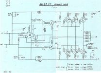
I am looking for an exact circuit description so as calculation rules of this topology. I haven't see similar topology by other commercial brands, and even not by diy projects. What is here very special (particularly benefits compare to others in respect to the sonic transmission) ??Is this any help?
Attachments
any news?I am looking for an exact circuit description so as calculation rules of this topology. I haven't see similar topology by other commercial brands, and even not by diy projects. What is here very special (particularly benefits compare to others in respect to the sonic transmission) ??
Musical Fidelity uses this topology by various other models like F16/F19 - P170/P270 and A370 - probably at some more models from those days.
here some URLs of the mentioned models:
?? P270-2 MUSICAL FIDELITY ????? ?????? McIntosh/JBL/audio-technica/Jeff Rowland/Accuphase/?/?¾?????
MyAVµøÅ¥°Ó±¡ºô - Musical Fidelity P270 (aÃþ«á¯Å)(¤G¤â/$00000000/®ç¶é¿¤)
Musical Fidelity P270
P270-2 MUSICAL FIDELITY HiFi-Do McIntosh/JBL/audio-technica/Jeff Rowland/Accuphase
http://www.diyaudio.com/forums/powe...x-poweramp-without-transformer-need-help.html
http://www.diyaudio.com/forums/solid-state/139506-musical-fidelity-p270-strange-power-off-noise.html
http://www.audiodesignguide.com/doc/ampl/musical_fidelity_a370.jpg (A370/F16)
http://www.diyaudio.com/forums/solid-state/24723-schematic-a370.html
http://peufeu.free.fr/audio/schemas/Audio_Research_D400a.JPG (Audio Research Power Follower D400)
Concerning the P170 on diyaudio there are this threads:
http://www.diyaudio.com/forums/solid-state/108565-musical-fidelity-p170-blown-transistors.html
http://www.diyaudio.com/forums/solid-state/75829-musical-fidelity-p170.html
http://www.diyaudio.com/forums/solid-state/167934-p170-power-amp-my-first-post.html
http://www.diyaudio.com/forums/solid-state/179863-musical-fidelity-p170-power-amp.html
http://www.diyaudio.com/forums/solid-state/59808-musical-fidelity-p170-power-amp.html
http://www.diyaudio.com/forums/solid-state/203049-musical-fidelity-p170-bias.html
Instead of OPA627's with pins 1, 5 and 8 not connected, could I use Dexa Class D discrete op-amps ?
If you did, I would watch for dc offset, use a varied or lightbulb tester on startup.
Have you done other modifications, ie power supply?
Have you done other modifications, ie power supply?
Hi Marcus,
I'd leave the LM318 in there. It is blazingly fast, around 70V / uS. If you replace it with another, you may need to redo the HF compensation.
I was never impressed with these toasters. There is not enough current to charge and discharge the gate properly. The driver stage is not well designed. This amp "is what it is".
-Chris
It's a fast one alright! the old BGW amps used a 318 as well, they were powerfull sounding but kind of, well, gritty sounding, which right or wrong I always blamed the 318 for that. They could also oscillate if there was flux on the board around their pins.
Any gear that old better plan on replacing all the electrolytics, I am repairing a Sony 3/4 inch U-matic VCR from the 80's right now and have found 21 (so far) bad caps.
sounds like you use the same method on burned boards that I do, cut out all the carbonized material, then place a peace of tape one the board and fill with epoxy. i have been 100% sucessfull with that method. Otherwize 0% success.
Which of the two circuits from the pdf attachment bears the signature ofI am looking for an exact circuit description so as calculation rules of this topology. I haven't see similar topology by other commercial brands, and even not by diy projects. What is here very special (particularly benefits compare to others in respect to the sonic transmission) ??
Tim de Paravicini ?
I think, the second circuit (Dr. Thomas) looks like Cyrus I and II so as Moth - thus it bears the signature of Mr. Stan Curtis. But I am nut sure.
...nevertheless the sound quality is very good - obviously the audible effects by the above mentioned disadvantages are seemingly quite small.Hi Marcus,
I'd leave the LM318 in there. It is blazingly fast, around 70V / uS. If you replace it with another, you may need to redo the HF compensation.
I was never impressed with these toasters. There is not enough current to charge and discharge the gate properly. The driver stage is not well designed. This amp "is what it is".
-Chris
Last edited:
There are other amps that use the lm318, and replacing it isn’t as straightforward as finding another part that typically sounds good.
There has been some work to provide better decoupling however, and on my project have found that a small (22uf) electrolytic from each rail to ground, along with a .01uf film from rail to rail works well.
There has been some work to provide better decoupling however, and on my project have found that a small (22uf) electrolytic from each rail to ground, along with a .01uf film from rail to rail works well.
P170 temperature measurements
My first post .
I recently acquired one of these and heard that they ran hot . so I measured the heatsink, driver transistors and an internal with various scenerios Lid on/off and also raised off the deck by 100mm and a fan cooling the internals - results are in the attachment.
- measured the 1k5 resistor which drops the @60v to 12v - and after 60mins with the lid on they measure @ 68c at 20c ambient (lid on) .
The bias was left at 61mv - my main concern was to see the effect of various thermal scenerios.
I hope these results are useful
cheers Steve
Attachments
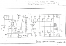
I have found this schematic for the A370.2 and P270.2 - it includes the current mirror circuit to reduce the 60v down to 12v .
And I think that the 4 x 1k5 5w resistors from +60v to Gnd are only there to aid power reservoir discharge - I'd imagine that without them there are dc thumps galore on switch on/off.
And I think that the 4 x 1k5 5w resistors from +60v to Gnd are only there to aid power reservoir discharge - I'd imagine that without them there are dc thumps galore on switch on/off.
Attachments
Are there original service manuals, circuit descriptions and schematics from Musical Fidelity's early amplifier models like this "P170" available in the meantime ?
- Home
- Amplifiers
- Solid State
- Musical Fidelity P170 Power Amp