+/- PS is out of balance
Hope y'all don't mind my working through this project "out loud" here. I measured the +/- supply today. The + side is about right (13.7v) but the - side is -11.7v. I don't know if this is cause or effect but it seems like the caps on the output of the - supply transistor might be a possible place to look. To go further I will have to remove the bottom plate of the case (the regulator section is covered by a metal sheild).
I am considering disconnecting the PS from the amp so that I can check whether the amp is pulling the voltage off or if the PS itself is faulty. Any down side to doing that? The connections are wire wrapped and I don't want to mess with unwrapping and rewrapping so I would plan to cut the connecting wires and then solder splice back together when done.
I also wonder if the wire wrap connections may be causing the problem. Do such connections loosen with time and introduce stray capacitance that could negatively affect the circiut?
mike
Hi Mike,
Interesting. The reference for the positive regulator seems to be the negative regulated output. Try and change the electrolytic caps in the regulator circuit. All except the main filter caps.
I can almost make out the component values. What model is this from? Or could you email me a full res. picture?
-Chris
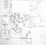
It is a Realistic STA-85. Attached is a closup of the regulator section which shown most of the values pretty clearly. To get a better overall I will have to wait until I can get to a flatbed and scan the whole schematic.
I am afraid it has been a loooonngg time since my EE classes so I am pretty clueless as to how this regulator works and I haven't yet had time to study it and figure it out. When I can devote a few hours to slogging through the circuit analysis maybe it will be clearer. In the mean time I need to disassemble a bit further so that I can gain access to all of the circuit elements and take complete voltage measurements and calculate all the currents and see what looks out of order. At that point I could probably access all the caps and at least replace the ELs.
mike
P.S. I really appreciate all of the help!

Hi Mike,
Believe it or not, I have a very small schematic of that model! The regulated outputs should be -14VDC and +14VDC. Don't expect these voltages to be exact by any means. The 3.3uF caps can be replaced by 4.7uF, that kind of thing.
TR804 outputs +13VDC for your tone control section. This circuit runs on +13VDC only.
-Chris
Did some more work on this
First thanks to all for your help.
It turns out that there is evidence of iced tea in this thing. I got some 91% Isopropyl and carefully cleaned the underside of the PCB getting all of the gunk off in hopes that the problem would clear up but to no avail. So I figured I might as well measure some more voltages before I start yanking out caps.
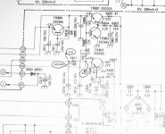
I am attaching pics of the schematic (preamp and regulator sections) with voltages noted. It does look like something is slightly amiss but they are not way out. The emitter of the input transistor should be at ground (and thus base at 0.6V) but the base is in fact at ground.
I also note that R811 in the regulator is listed at 100 ohms but is in fact a 220 ohm resistor. This resistor is dropping about 2 volts so the negative supply to the preamp section appears to be drawing about 10ma. Does that sound about right or a little high? Nothing seems to be getting hot.
mike
First thanks to all for your help.
It turns out that there is evidence of iced tea in this thing.
I got some 91% Isopropyl and carefully cleaned the underside of the PCB getting all of the gunk off in hopes that the problem would clear up but to no avail. So I figured I might as well measure some more voltages before I start yanking out caps.I am attaching pics of the schematic (preamp and regulator sections) with voltages noted. It does look like something is slightly amiss but they are not way out. The emitter of the input transistor should be at ground (and thus base at 0.6V) but the base is in fact at ground.
I also note that R811 in the regulator is listed at 100 ohms but is in fact a 220 ohm resistor. This resistor is dropping about 2 volts so the negative supply to the preamp section appears to be drawing about 10ma. Does that sound about right or a little high? Nothing seems to be getting hot.
mike
Attachments
Shorting the power first stage, the input, normally help to eliminate power as...
The cause, in this case of noise generated.
But some noise can be generated in this first stage that you have the input to ground, this can stop oscilation sometimes.
Please, remove the input resistor of both channels, dessoldering only one side, and check for noises.
See the power, there are two resistors and one cap in series with the first stage supply, if this small condenser is dried, your first stage can oscilate and produce noise too.
Yes, of course your test was perfect...putting to ground power amplifier input you also eliminate hissing from earlier stages...and more probable, the cause will be earlier stages, but i faced this problem once in my life, the first stage oscilated...and shorting input i stopped the oscilation...i remember that this turns me crazy for more than a week!
Good luck!
Carlos
Thanks Carlos and Chris.
Carlos, do you want me to open the input to the preamp section or the power amp section?
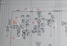
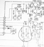
Is one of the circled caps in the attached image the one you think might be dried out?
I was considering removeing the larger one and seeing what happened (would obviously remove some filtering but I thought that if it were leaking and causing the problem I should see a drop in hiss also). Is that the kind of check you were thinking of or something else?
mike
Carlos, do you want me to open the input to the preamp section or the power amp section?
Is one of the circled caps in the attached image the one you think might be dried out?
I was considering removeing the larger one and seeing what happened (would obviously remove some filtering but I thought that if it were leaking and causing the problem I should see a drop in hiss also). Is that the kind of check you were thinking of or something else?
mike
Attachments
Well my dear Mashaffer, if things turns too much hard, i use the definitive solution.
Of course, each one of us with their own methods.
Capture my meaning, if something disturb too much, give enormous work, and pleasure is going away.
The tool.... yeah!
kidding
regards and good luck
Carlos
Of course, each one of us with their own methods.
Capture my meaning, if something disturb too much, give enormous work, and pleasure is going away.
The tool.... yeah!
kidding
regards and good luck
Carlos
Attachments

FIXED!
It looks like we have it fixed. I did use salvaged parts so I may have to do it again later but the hiss is gone and it appears to be working properly. I didn't have money for new parts until payday so I figured I might as well see what I could do with the stuff in my parts bin.
It is currently playing through my crappo polk computer speakers so I won't know how it really sounds until I connect to something better but I don't think that anything that I did could have caused the sound quality to be messed up.
I replaced the three caps suggested as well as C808. The new values are...
809 and 810 = 470uF
814 = 47uF
808 = 10uF
I also removed TR802 and cleaned up some gunk that was on the leads. While it was out I tested it. It checked out OK with Hfe of 117 so I put it back.
Before putting in the new (used) parts I cleaned the exposed top side of the circuit board with isopropyl since I could get in with the parts out of the way. Cleaning the entire board was out of the question.
So I don't know which part was failing (or if the cleaning did the trick) but I am gratified and grateful that we got her going.
I figure that if the problem comes back I will go in with new parts. At least I will know right where to go.
Love your sense of humor Carlos! However, if it hadn't worked I was planning on just using it as a tuner and building my own preamp.
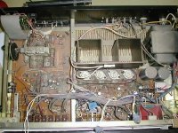
A picture of the top side.
I just had a thought. The hiss is the same in both channels so I wonder if that would implicate a PS issue since the chance of both preamps failing in the same way seems remote. Any merit to that line of thinking?
mike
hello, a question: what are the number of the audio transistor, please i need this number.
thank´s in advance!
sorry for my poor English.
Attachments
IMO, yes. After fixing the hiss it has been in use as a woofer amp in my main setup. The best feature of this rcvr is probably the amp section as it is a nice simple design with discreet components throughout. Don't have the schemo right at hand but IIRC the tuner sections were ICs but performance was still decent.
I haven't used the Phono section in quite a while as it has not been the front end in my setup for years but my recollection was that it didn't have any bad habits when paired with entry to mid grade Shure carts.
If not to expensive to resurrect I would do so.
mike
I haven't used the Phono section in quite a while as it has not been the front end in my setup for years but my recollection was that it didn't have any bad habits when paired with entry to mid grade Shure carts.
If not to expensive to resurrect I would do so.
mike
- Status
- This old topic is closed. If you want to reopen this topic, contact a moderator using the "Report Post" button.
- Home
- Amplifiers
- Solid State
- Debugging hiss in old receiver