Michel
Wow that was quick !
Does it have DC on both channels?
Not sure - I have a dc protection device and it triggers, I am away from home for 2 months so won't have access to a volt meter until then.
I could connect the speakers directly one by one and see the effects but I don't want to risk them !
It does that when the speakers are connected, right?
Yes, it causes a large thump with large cone movement.
What is the impedance of your speakers?
Nominally 8ohms (Tannoy Saturn)
Graham
Graham,
The A28II uses a unipolar power supply.
The drawback of that topology is that you have to use a large value capacitor to couple your amplifier to your speakers.
Every time you power on your amplifier this capacitor goes from no voltage on both sides to approximately half VCC to the connection inside the amplifier (output of the amplifier) while the outside connection (connected to the speaker) tries to stay to zero.
All this happens fairly quickly and explains why you always have a thump when you power on you amplifier.
As for how long there will be some residual voltage i can not answer that as I have never measured it.
20 seconds seems a rather long delay for the voltage to disappear but still without any measurement done while this is happening I can not give a more precise diagnostic.
Do the output capacitors still have a flat top?
If my memory is good there are 10 mF caps in the power supply section and 4m7 caps for the output coupling.
Michel
Michel
The two Rubycon 4700 mF capacitors next to the transformer (near front of amp) no longer have a flat top. I am looking at a picture as the amp is currently playing music !.
Are these the output caps (due to their position the obvious thing to think is that they are psu caps !) - I am assuming that the 10000 mF caps are the psu smooting caps - at the back of the amp.
The amp still sounds good, you mentioned in a previous post that the output caps will affect tonal quality so is it best to stick to 4700mF ?
Thanks.
Graham
Graham,
I just had an idea.
You are talking about a dc protection device and there has never been such a circuit inside an A28II...
I think I know what is happening...
Every time you power on your amplifier, the external protection kicks in because it is detecting some voltage at the output of your amplifier.
The problem is that when your device activates, the output becomes floating and takes much longer to discharge because it is not loaded by the speakers.
It could stay in protection mode forever but there are resistors soldered to the binding posts that eventually discharge the capacitors.
It takes much longer because the value of those resistors is much higher than 8 ohms.
This is probably why it takes 20 seconds before the protection goes back to normal.
If you find this long delay annoying, you should install 47 ohms resistors to the active connection of the relay that is used in your DC protection device.
This way it could take only seconds before it deactivates.
Be careful not to be mislead by a bumped plastic cover on the output capacitors.
Some of the capacitors had plastic covers on top of them and only these would bump while the aluminum case would still have a flat top under it.
As I often say, if it ain't broke, don't fix it!
Regards,
Michel
Michel
Yes - well spotted that man !
Now you mention it there are some bleed resistors in the protection device (its only a Velleman K4700 - I knocked it up the other day as i was concerned...) , but they are currently disconnected as I wasn't sure of the psu topology. They are only used for single rail supply amp, connecting them will have the same effect as your 47 ohm resistors.
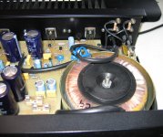
The 4700 mF caps are metal cans and they are bulging slightly, as I originally thought they were the psu caps and the transformer makes a bad buzz on start up I thought they were dead, they may well be. The attached pic should show it ok.
You have been a real help - the schematics will still be v. useful though.
Graham
Yes - well spotted that man !
Now you mention it there are some bleed resistors in the protection device (its only a Velleman K4700 - I knocked it up the other day as i was concerned...) , but they are currently disconnected as I wasn't sure of the psu topology. They are only used for single rail supply amp, connecting them will have the same effect as your 47 ohm resistors.
The 4700 mF caps are metal cans and they are bulging slightly, as I originally thought they were the psu caps and the transformer makes a bad buzz on start up I thought they were dead, they may well be. The attached pic should show it ok.
You have been a real help - the schematics will still be v. useful though.
Graham
Attachments
Graham,
Glad I could help!
We are still not done...
On close inspection of the picture you sent me I can clearly see the power transistors insulators. Replace them and the quicker the better. They are not up to the task and can pierce at any time. Very bad choice on the part of Sugden at the time... Use the good old micas instead.
The first thing that would indicate that your output capacitors may have lost some of their nominal value is a loss in the bass section. As the value of the capacitor declines, the low frequency cutoff gets higher. If you find the amp sounds good, leave them alone.
It sure would not be a bad thing to replace the filter capacitors but make sure you check all the other ones as they may be at the end of their useful life too.
I had to replace zillions of them and I still do. Sometimes they are easy to spot because they change color but they may look like new and still be bad. I know it is time consuming but very important you do it as it may be the source of your buzzing...
As for the filter capacitors I would much prefer to install some with 100 V rating but the ones I can find have a diameter that is simply too big. Another thing that I surely have mentioned before in the thread, always replace passive parts in pairs. Whatever you do on one channel replace it on the other one, unless you are using a part of the same origin. I would not be fussy with the capacitors and replace them in pairs anyway.
I will send you the schematic(s) next Monday as I have to be at work to do that.
Regards,
Michel
Michel
I shall replace the insulators as soon as I can get some, I shall also connect the bleed resisitors and let you know the outcome, maybe tomorrow if I get time.
The sound is ok with plenty of bass (almost too much) but the amp does not sound quite as good as I expected so maybe a little caps servicing will help.
Thanks in advance the schematics.
Graham
Michel
I have just connected the bleed resistors - and, surprisingly, it did not have the expected effect, it still took considerable time for the dc voltage to settle, but at least it is stable after that.
I note from your previous posts that you mention the 80v caps are too close to the rail voltage, for the output caps 80v should be fine as surely the voltage is unlikely to be anywhere this very often, unless it was clipping of course.....
Graham
Graham,
The 80 V caps are not for the output but for the power supply.
The 35 V caps are the output capacitors.
Michel
My mistake, I had assumed that they were both 80v, and also that the 10000 mF were the psu caps.
Anyway they will be replaced as things have got a little worse with the transformer buzz periodically returning, I am not using it again until I have had a proper dig around inside.
Graham
2 bridged P28 to drive JBL L90?
Hi,
since the sugdens aren't very common in Germany I try to get some informations here. I have one P28 (back heat sink) and the JBLs and I think the sugden is not the best way to get the most out of the JBLs. Shall I look for another P28 to bridge both or is it better to search a bigger Amp but with sugden sound?
TIA
Thomas
humming p28
You guys seem to have a lot of experience on the P28 of Sugden. I just bought a secondhand P28 with heatsink on the back. I have a circuit diagram. All values (idle current around 300mA etc) are all right. The amp does give a normal sound on both channels. But .... both channels give a terrible hum always in the background. Strange, because both channels are built completely separate, so both channels share the same problem. I can get the hum away almost completely if I use a 4700mF 3R3 4700mF arrangement in the powersupply. Only changing the existing 4700mF for a new one does not solve the problem. I must say I use high sensitive Klipsch speakers but the hum is far higher than normal. I guess a few possibilities:
1. I am overly critical at hum, everybody else can live with it.
2. There is some other cap in the amp that has gone bad (power supply related), but then this must be the case in both channels at the same time and in same amount. Seems strange to me.
Can anybody help me out with this?
test the power amplifier alone.
Remove the speakers, remove the input cables.
Insert a shorting plug to the input RCA socket/s.
Measure the output offset (DC) and noise (AC) at the speaker terminals.
If you have one use a 199.9mVdc and 199.9mVac scale on your DMM.
If both noise and offset are very low, then connect a speaker and listen to hear the noise. Is it LF or wideband, is it pure tone or is it buzz?
Remove the speakers.
Remove the shorting plug/s.
Check to see if the measurements have changed.
If the offset and noise are still very low connect a speaker and listen to the noise, same questions.
solved!
Thanks for thinking along. It indeed was the next capacitor down the line. A type 470mF/25V that feeds the input-section. These caps looked allright but after desoldering them they felt very light and dried out. Putting new caps in removed the problem. Lesson learned 1: it is possible to compensate a bad cap further down the line by putting a lot extra caps in front of the line (not wise), lesson learned 2: even good looking caps can be bad after all.
Thanks for thinking along. It indeed was the next capacitor down the line. A type 470mF/25V that feeds the input-section. These caps looked allright but after desoldering them they felt very light and dried out. Putting new caps in removed the problem. Lesson learned 1: it is possible to compensate a bad cap further down the line by putting a lot extra caps in front of the line (not wise), lesson learned 2: even good looking caps can be bad after all.
P28 - intermittent channel failure
Hi All,
Great to find other owners of Sugden products and people that are willing to provide their knowledge and support.
I have two P28's - heatsinks on the rear and am having similar issues to many people within this thread.
First off - it would be wonderful if someone could provide me the schematics for this amplifier as I am likely to need this for the future.
Secondly - the right channel is the intermittent one. Generally resolved by either giving it a sharp tap on the lid (undesirable - ) or by increasing the volume till the channel kicks in, but then fails again when the volume is reduced.
Also, works just fine sometimes (last night for example)
From what I have read - order to approach diagnosis/repair would be:
- Check speaker protection relay
- Check fuse holder
- Check input stage transistors
- if ok, check transistor bias
Any other tips would be very welcome.
cheers,
Scott.
e-mail for schematic - s c o t t . j e r o me @ t h r e e . c o m . a u
Hi All,
Great to find other owners of Sugden products and people that are willing to provide their knowledge and support.
I have two P28's - heatsinks on the rear and am having similar issues to many people within this thread.
First off - it would be wonderful if someone could provide me the schematics for this amplifier as I am likely to need this for the future.
Secondly - the right channel is the intermittent one. Generally resolved by either giving it a sharp tap on the lid (undesirable -
) or by increasing the volume till the channel kicks in, but then fails again when the volume is reduced.Also, works just fine sometimes (last night for example)
From what I have read - order to approach diagnosis/repair would be:
- Check speaker protection relay
- Check fuse holder
- Check input stage transistors
- if ok, check transistor bias
Any other tips would be very welcome.
cheers,
Scott.
e-mail for schematic - s c o t t . j e r o me @ t h r e e . c o m . a u
Hello, I've just got the A28II and it looks like the quiescent current is set very low, everyone say that these run hot and mine is dead cold.
I've seen that I should set it for 300mA/channel?
I'm more confident in measuring the voltage drop on the resistors? can someone measure the voltage drop on the big resistors near the output transistors?
Also which pot is for quiescent current and which one for DC offset?
Thanks
I've seen that I should set it for 300mA/channel?
I'm more confident in measuring the voltage drop on the resistors? can someone measure the voltage drop on the big resistors near the output transistors?
Also which pot is for quiescent current and which one for DC offset?
Thanks
Last edited:
idle current
I think there are different versions of the 28 around. The idle current should be around 300 mA. If I remember correctly the bigger resistors (2 Watt) are either 0.2 Ohm of 0.33 Ohm. The voltage DC across these resistors should therefore be 60 mV or 100 mV (depending on which value the resistor has).
I think there are different versions of the 28 around. The idle current should be around 300 mA. If I remember correctly the bigger resistors (2 Watt) are either 0.2 Ohm of 0.33 Ohm. The voltage DC across these resistors should therefore be 60 mV or 100 mV (depending on which value the resistor has).
Oh yes, about the potmeters. There is no offset on the 28 because it's an capacitor coupled amp at the output (10.000 uF per channel). You discover soon enough which pot is for what. The what you call offset pot is to get half of the V+ (around 70V) at the point where the 2 big resistors are connected to each other (at that point around 35V by turning the pot). The other pot therefore is for idling current. Just try very carefully to change the pot a little bit and measure the voltage across the big resistors.
You can increase the idle current as long as that after one hour or so the temperature at the back of the amp is 50-55 degrees maximum.
Watch out: increasing the idle current is a matter of millimeters, sometimes just by tapping at the pot the current increases or decreases.
You can increase the idle current as long as that after one hour or so the temperature at the back of the amp is 50-55 degrees maximum.
Watch out: increasing the idle current is a matter of millimeters, sometimes just by tapping at the pot the current increases or decreases.
- Home
- Amplifiers
- Solid State
- Sugden P28