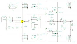
A problem with this topology is that the current-stabilising output resistors have their voltage drop divided by whatever gain has the OP stage.
In the early example I posted, this leads to large, high power resistors (1 ohm 10W):
This is not a problem in a sim, where there is no risk of thermal runaway, but a real amplifier should tackle the problem in an acceptable way.
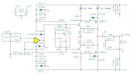
I tried to replace the feedback resistors with an active circuit (quintupole or pentapole?) having the same behaviour as the resistors in the horizontal direction, but acting as a direct connection in the vertical direction (common-mode and differential-mode, but which is which?).
It kind of worked, but the active circuit introduced unwanted non-linearities.
It is an alley worth exploring more thoroughly if a good, usable circuit is to be developed.
In the early example I posted, this leads to large, high power resistors (1 ohm 10W):
This is not a problem in a sim, where there is no risk of thermal runaway, but a real amplifier should tackle the problem in an acceptable way.
I tried to replace the feedback resistors with an active circuit (quintupole or pentapole?) having the same behaviour as the resistors in the horizontal direction, but acting as a direct connection in the vertical direction (common-mode and differential-mode, but which is which?).
It kind of worked, but the active circuit introduced unwanted non-linearities.
It is an alley worth exploring more thoroughly if a good, usable circuit is to be developed.
Also, one practical observation from my build of "Square Law Amp", is that all this extra compensation and snubbers making OS stable, were slowing it down.
Slew rate was barely above 10V/us
Seems the actual snubber that stabilized the amplifier was set
around 120 kHz
likely majority of the other snubbers can be removed.
or raise the frequency of the snubber that stabilized the amplifier slightly
to 220 or 300 kHz
Its possible or would seem most the Slew Rate would be limited to the Opamp
I believe you used a TL0 XX series opamp which are limited to around 10 to 12V/ us
That was the original attraction to this topology.
Without needing to build a discrete frontend.
Its likely using a opamp like a LM7171
Which has a Slew Rate of 4100 V/ us
could offer a rather high slew rate.
I believe the TLOxx series has a bandwidth of around 700 kHz
when the 7171 climbs up to around 200 MHz
Which is no big deal, the amplifier needs to be limited to 150 to 300 kHz for stability
Its ok I already embarrassed myself by trying to improve slew
rate. Blasting the drivers with too much current in simulation.
kind of wasn't paying attention....ooops
Last edited:
This got me thinking about another thread re a op-amp +quasi MOSFETs. I simulated a working circuit but it still needs work so I'll post it later. A CFP with gain deals with MOSFET bias issues but you can't put gain on one side only so you have to add a PNP to the top side (3 transistor CFP).
One important thing I ran into is the importance of simulating 10KHz+ where the op-amp has to work harder and needs more CFP gain.
One important thing I ran into is the importance of simulating 10KHz+ where the op-amp has to work harder and needs more CFP gain.
- Home
- Amplifiers
- Solid State
- The " Forbidden" Topology! Arm Wrestle the Devil