I came across this blog. Current dumping for dummies? – CONNERLABS
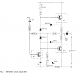
The most well-known implementation of "Current Dumping" is Quad 405.
The "Current Dumping" topology claims to eliminate the crossover distortion with no idle current at output stage. Is that true? or just a marketing things?
Here is my little experiment.


It holds its claim pretty well. 0.002% THD@10KHz under +-20Vp-p.
The number is even better than an average Class B amp.😱
The most well-known implementation of "Current Dumping" is Quad 405.
The "Current Dumping" topology claims to eliminate the crossover distortion with no idle current at output stage. Is that true? or just a marketing things?
Here is my little experiment.
It holds its claim pretty well. 0.002% THD@10KHz under +-20Vp-p.
The number is even better than an average Class B amp.😱
Jumpstart yourself to https://www.diyaudio.com/forums/sol...phile-approach-perfect-sound.html#post6718085
Jan
Jan
So basically a bridge where the balance is between the class A and class B.
So when the class A sine wave occurs, the class B then attempts to balance with current “dump”?
I was always wondering if a Fontana bridge could be used to drive a current stage.
So when the class A sine wave occurs, the class B then attempts to balance with current “dump”?
I was always wondering if a Fontana bridge could be used to drive a current stage.
It is a balance between two gains, two feedback factors.
The effect is that when the dumpers come on, the bridge reduces the feedback factor by the dumper gain factor, so there is no longer a difference between loop gain in the two situations.
I find Steve Conner's explanation the best, clearest and most succinct I've seen so far.
But as with all things in life, nothing is perfect, and the performance of the whole amp is limited by the class A driver amp performance.
In the 405-2 Walker used a single diode bias to keep the dumpers from completely shutting off, easing the demands on the class A driver.
Jan
Last edited:
Ok I think i got this - essentially the dumpers are filling in missing current identified by the error (bridge). Thus the class B “dumper” provides the corrective action to the desired gain.
Output impedance problems that occur when normal CF class B push-pull switches on/off during class A zero transition is then kept to a minimum by following the gain of the class A.
Output impedance problems that occur when normal CF class B push-pull switches on/off during class A zero transition is then kept to a minimum by following the gain of the class A.
Last edited:
Looks just like some very old technology designed and patented by Quad in the UK.
The Quad 303.
No it is completely different. The crux of the thing is the bridge in the current dumping concept.
The 303 is 'old school' with a bias trimmer to set the quiescent current in the output devices.
The 405 aims to delete the adjustment requirement (for reliability and manufacturing cost reasons, as Walker admitted), by using a class B output stage.
Jan
Last edited:
Ok I think i got this - essentially the dumpers are filling in missing current identified by the error (bridge). Thus the class B “dumper” provides the corrective action to the desired gain.
Output impedance problems that occur when normal CF class B push-pull switches on/off during class A zero transition is then kept to a minimum by following the gain of the class A.
The wrinkle in a 'normal' class AB output comes from the very non-linear input impedance of the output devices in the crossover region.
You could explain current dumping in another way, that the non-linear base input current of the output devices is now transferred to a very non-linear load current on the class A driver.
That is also the reason that the class A driver is the limiting factor in the total amp performance.
I've also experimented with a trimmer cap and trimmer resistor in the bridge, and you can really tune it for unmeasurable distortion. So it is important to use accurate value parts in the bridge.
Jan
I remember there is a way of moving a class AB crossover to a value of signal voltage that is not zero volts. Crossover happens at an input voltage that would produce some appreciable volume but much less than an amplifier's full power rating. This is done by pulling the output towards a rail as far as I remember using a resistor or better a stable current source.
Last edited:
I remember there is a way of moving a class AB crossover to a value of signal voltage that is not zero volts. Crossover happens at an input voltage that would produce some appreciable volume but much less than an amplifier's full power rating. This is done by pulling the output towards a rail as far as I remember using a resistor or better a stable current source.
Yes, Doug Self has implemented that in some of his commercial designs for Cambridge Audio. It's called class XD I believe (xover displacement).
Jan
Edit to the above: I realized that this is exactly what we do with opamps, to draw a small constant current from the output to make it work partly in class A. It displaces the xover point away from zero output. With opamps, you can actually draw so much constant current that it always stays in class A. With power amps, that will be prohibitive in terms of power dissipation.
IIRC Self uses a few 100mA constant current.
Jan
IIRC Self uses a few 100mA constant current.
Jan
Class AB output stages employ the emitter follower transistor configuration. Reading this thread I conclude or better learn that the input impedance is very non-linear for near zero collector currents. I must assume, this behaviour is due to the emitter base input characteristic which almost allows no current to flow for an appreciable input voltage. The latter makes biasing mandatory.
Simulating on LTSpice confirms that this is the case.
Simulating on LTSpice confirms that this is the case.
Last edited:
Ed, there are AB amps with collector follower output stages. The definition of class AB says nothing about the circuit topology, only that the conduction angle is (just above) 180 deg.
There are other topologies that do not need biasing, like the current dumping discussed here, Castor-Perry's class i, or Sandman class S.
In the heydays of solid state amp design, there was a lot of effort to try to get rid of the adjustable and drifting biasing.
Some survived, some didn't, partly because they were too complex for the occasional designer.
But whatever the system, all these concepts can lead to excellent amplifiers, for sure!
Jan
Last edited:
My amplifier project uses collector followers in the output although they have 0.22R wirewound resistors connected to their emitters and the respective rails.
I am convinced the driver stage is the most important to look at to decide whether an amplifier is Class AB or not. In my amplifier project, although the output is of the collector follower type, the driver stage is certainly an emitter follower or better a totem pole.
Regarding the need of BJT biasing, an amplifier circuit must take into consideration that BJTs cannot conduct for very low EB voltages and that they are not linear devices. Circuits which do not employ resistor chains or pulling resistors, must provide other means. This other means, although not technically described as a bias, is meant to achieve linearity and signal fidelity which are the same aims of biasing.
Performance is quite good but very tetchy to set up.
I think an EFII is actually hard to beat.
HD
In your simulation, Q1 and Q2 are just like simple CFP configuration. Thus, you can remove Miller cap C5. It will remain stable. Some small overshoot is OK, and overshoot will not be visible at speaker terminal because of the coil.
I find the extra Miller cap is equivalent to add more cap to the feedback bridge. It unbalances the bridge. Also it reduces slew rate at the input of EF2. Without idle current, it needs slew rate to cover the dead zone to achieve low THD.
Last edited:
I am convinced the driver stage is the most important to look at to decide whether an amplifier is Class AB or not.
With all due respect Ed, it's hard to have a meaningful discussion if you use a private definition of class (A)B that differs from the definition for the rest of us.
Class A is where the output stage conducts over the whole signal cycle, class B is when each half of the output stage conducts for half the signal cycle, with AB just a bit above that. The actual circuit topology is irrelevant for this classification.
But we should no longer derail this thread, it's about Current Dumping, after all.
Jan
Last edited:
Seems like a rather amazing simply circuit for .002 distortion
Very close to Amazing
Seems like L1 and R3 at 10u / 100R would severely limit the bandwidth of the amplifier
I wouldn't expect more than .1 % distortion at 10 kHz or 20kHz
Is 1 Farad needed for the output?
Its really a smart little circuit, and I can see why it would have DC offset
But assume something smaller than a Farad is needed.
I understand its a quick model, then of course wondering if 100ma of current
over 1N4148 diodes is at their current limit
Last edited:
- Home
- Amplifiers
- Solid State
- Current Dumping, Class A Performance With No Idle Current